Etching Process: Etching process requires the use of chemicals, acid resistant dishes and a running water supply. Ferric chloride is the maximum used solution, but other enchants such as ammonium sulfate can be used.
Nitric acid can also be used but in general it is not used due to the poisonous fumes. The pattern prepared is glued to the copper surface of the board using a latex type of adhesive that can be cubed after use. The pattern is laid firmly on the copper, use vary sharp knife to cut round the pattern carefully and remove the paper corresponding to the required copper pattern areas. Then apply the resist solution clean outlines as for as possible. While the board is drying to test all components. Before going to the next stage, check the whole pattern and cross check against the circuit diagram check for any foreign matter on the copper. The etching bath should be in a glass or enamel disk. If using crystal of ferric chloride these should be thoroughly dissolved in water to the proportion suggested. There should be 0.5 Lt. Of water for 125 gm of crystal. The board is then immersed in FeCl3 solution for 12 hours, in this process only the non hidden copper portion is etched out by the solution.
2FeCl3 + 2H2O + 3Cu 0 3CuCl2 + 2Fe (OH) 2
Waste liquid should be thoroughly diluted and buried in water land never pour down the drain. To prevent particles of copper hindering further etching, agitate the solutions carefully by gently twisting or rocking the tray. The board should not be left in the bath a moment longer than is needed to remove just the right amount of cooper. In spite of there being a resist coating, there is no protection against etching away through exposed copper edges; this leads to over etching. Have running water ready so that the etched board can be removed properly and rinsed; this will halt etching immediate.
Now the paint is washed out by the petrol. Now the copper layout on PCB is rubbed with a smooth sand paper slowly and lightly such that only the oxide layers over the Cu is removed. Now the holes are drilled at the respective places, according to component layout as shown in figure. Drilling is one of those operation that calls for great care, because most of the holes will be made and vary small drill. For most purpose a no. 60 drill all holes with this size first those that need to be larger can be easily drilled again with the appropriate large size.
Component Assembly: There should be no damage, such as hair line crack in the copper on PCB that could have a serious effect on the operational ability of the completed assembly holes.
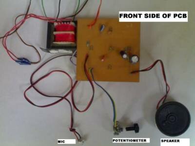
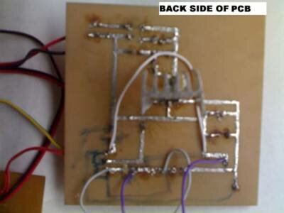
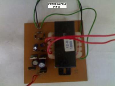
Some photographs:


If there are, than they can and should be repaired first, by soldering a short link of bare copper wire over the affected part. The most popular method of holding all the items is to bend the wires further apart after they have been inserted in the appropriate holes. This will hold the component in position ready for soldering.
Some component will be considerably larger than others, occupying and possibly partly obscuring component. Because of this, it is best to start by mounting the smallest first and progressing through to the largest, before starting, makes certain that no further drilling is likely to be necessary, because access may be impossible later. When filling each group of components, mark off each one on the components list as it is fitted and, if we have to leave the job, we will know where to recommence.
Although transistors and integrated circuits are small items, there are good reasons for leaving the soldering of these until the last step. The main point is that these components are varying sensitive to heat and if subjected to prolonged application of the soldering iron, they could be internally damaged. All the components before mounting are rubbed with sand paper so that oxide layer is removed iron their tips. Now they are mounted according to the components layout.
Project by: Sanjay Yadav, All Saints’ College Of Technology, Bhopal.
All Saints’ College Of Technology

hi im in search of a project for my 8th sem based on microcontrollers please can anybody give me suggestions……………if u have an idea please sennd to my id mentioned above.
Visit this link, u could make money 4rm it witout sweat.
http://incomepart.com/ref.php?page=act/ref&invcod=135974
Welcome to Michael Kors Outlet Store and take the nice Michael Kors Handbags for Collection!
Welcome to go shopping in our Michael Kors Outlet Store! In order to give consumers the best service; we offer the series of Michael Kors top designing Products. The elegant Michael Kors Handbags, Michael Kors Wallets and Michael Kors Totes will give you a big surprise. Many fashionable styles and beautiful appearance will make your eyes so pleasure at the first sight.
This Michael Kors Bags are easy to fit your dressing when you take part in evening party or society action. Any Michael Kors Goods for sale here is wonderful for the classical and valuable collection. Most of all, we believe that we will give you the top authentic Michael Kors Clearance Goods and enjoy the biggest discount. Go shopping here will be a permanent memory in your life.
I m also looking for micro-controller project ….Some one please help me …Electrical Engineering 4th semester ….!