Here is a simple project to detect the object using the IR sensor module.
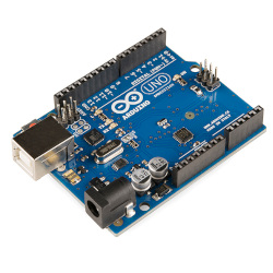
Components required:
Principle:
IR sensors are used in the detection of objects, and obstacles. IR light is emitted from the IR emitter, which falls on the object and then reflects back. This reflected IR light is captured using an IR receiver and used to conclude the presence of the object. If the object is in the vicinity of the IR module, then the object’s presence can be detected. Otherwise, the object is said to be absent.
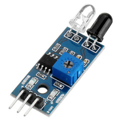
The IR sensor module has an IR emitter and receiver in the same module. The diagram below shows the IR sensor module.
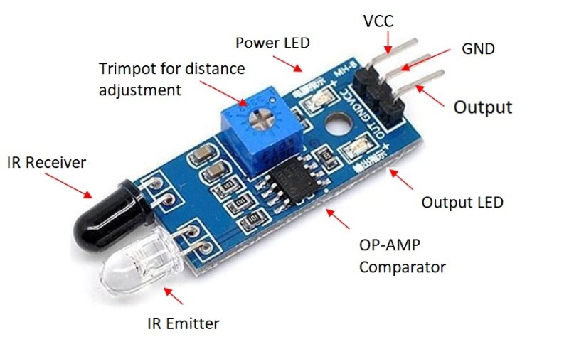
The IR module contains 3 pins for the interface. Out of 3 pins two pins are VCC (3.3V/5V) and GND power supply. The OUT pin is the output pin which goes to a HIGH state when the object is present. When no object is detected OUT pin will stay at a LOW state. The major components in the module are the OP-AMP comparator, trim-pot, power LED and output LED. Trim-pot is used to change the sensitivity of the IR module (by varying the trim-pot we can change the distance at which the sensor can detect the object).
Circuit diagram:
Procedure:
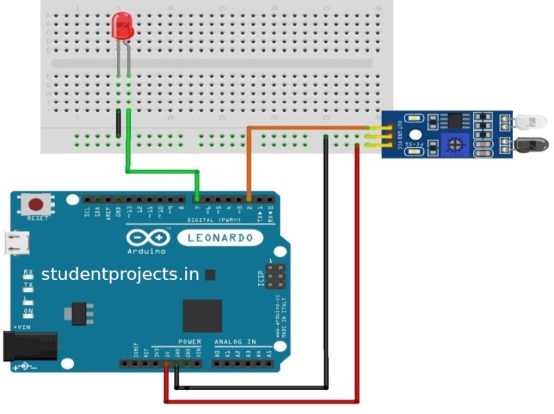
- Connect the IR module’s VCC and GND pins to Arduino’s +5V and GND pins respectively as shown in the circuit diagram.
- Connect the OUT pin of the IR module to the Arduino board (pin 2) and declare it an input pin.
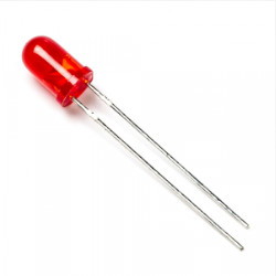
- From the Arduino board connect the output (pin 7) to the +ve terminal of the LED. Connect –ve terminal of the LED to ground
- Write the code in Arduino UNO software and run the program.
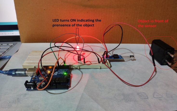
- Move the object in front of the IR module and see the LED turning ON which indicates the presence of the object.
Working of object detection:
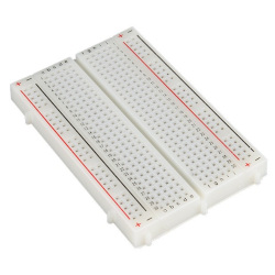
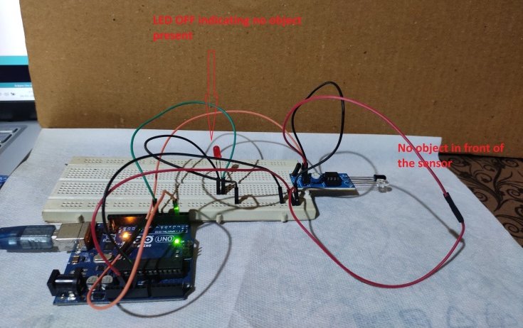
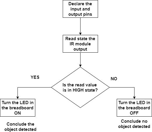
Whenever there is an object in front of the IR module, OUT of the IR module goes high. The IR module’s OUT pin is connected as the input to the Arduino board. The microcontroller in the Arduino board reads this signal and can conclude whether there is an object or not. The output is indicated through the LED connected to the Arduino board (shown in the breadboard).
The distance of the measurement (sensitivity) can be changed by varying the trim-pot. Variation in the trim-pot changes the reference voltage of the OP-AMP comparator. This
Flowchart for object detection:
Arduino Program for object detection:
int in_IRSensor = 2; // connect ir sensor to arduino pin 2
int out_LED = 7; // conect Led to arduino pin 13
void setup()
{
  pinMode (in_IRSensor, INPUT); // sensor pin INPUT
  pinMode (out_LED, OUTPUT); // Led pin OUTPUT
}
void loop()
{
  int status_IR = digitalRead (in_IRSensor); //Read the IR sensor output
  if (status_IR == 1)
  {
    digitalWrite(out_LED, HIGH); // high on LED indicates object detected
  }
  else
  {
    digitalWrite(out_LED, LOW); // low on LED indicates no object present
  }
}