GPS – AN OVERVIEW
The GPS (Global Positioning System) is a “constellation” of 24 well-spaced satellites that orbit the earth and make it possible for people with ground receivers to pinpoint their geographic location. The location accuracy is anywhere from 100 to 10 meters for most equipment. Accuracy can be pinpointed to within 1 meter with special military-approved equipment .GPS equipment is widely used in science and has now become sufficiently low-cost so that almost anyone can own a GPS receiver.
The GPS has three components namely: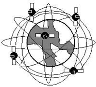
- The space segment: consisting of 24 satellites orbiting the earth at an altitude of 11000 nautical miles.
- The user segment: consisting of a receiver, which is mounted on the unit whose location has to be determined.
- The control segment: consists of various ground stations controlling the satellites.
The GPS is owned and operated by the U.S Department of Defense but is available for general use around the world. Briefly, here’s how it works:
- 21 GPS satellites and 3 spare satellites are in orbit at 10,600 miles above the earth. The satellites are spaced so that from any point on earth, 4 satellites will be above the horizon.
- Each satellite contains a computer, an atomic clock and a radio. With an understanding of its own orbit and the clock, it continually broadcasts its changing position and time. (Once a day, each satellite checks its own sense of time and position with a ground station and makes any minor correction).
- On the ground, any GPS receiver contains a computer that “triangulates” its own position by getting bearings from 3 or 4 satellites. The result is provided in the form of a geographic position- Longitude and latitude, for most of the receivers, within 100 meters.
- If the receiver is also equipped with a display screen that shows a map, the position can be shown on the map.
- If the 4th satellite can be received, the receiver/computer can figure out the altitude as well as the geographic position.
- If you are moving, your receiver may also be able to calculate your speed and direction of travel and give the estimated times of arrival to specified destinations.
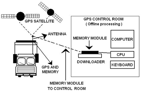
For a GPS receiver to function, it needs to lock onto satellite signals. Each satellite broadcasts two signals at 1.57542GHz and 1.2276GHz, denoted as L1 and L2, respectively. A satellite specific code, known as the course acquisition (C/A) code, is used to discern satellites. Correlation of the transmitted codes against local codes is needed to locate satellites in frequency space. The 1023 bit C/A code modulates the L1 at 1.023MHz, repeating every millisecond. Accumulation of this 1000Hz data is required for a receiver to operate.
Once the GPS receiver made the calculation, it can tell the latitude, the longitude and the altitude of its’ current position. This doesn’t tell much to the average user. So in order to make use of the GPS receiver more user-friendly many receivers send this data to a program which displays a map and can show the position on it. Geographical Information System (GIS) is a computer-based software capable of handling maps and various details given on the map. Data generated by the GPS use spatial data referenced to the earth. In other words this data is the coordinates of its own position expressed in latitude and longitude. This data needs to be positioned on a map of the area for any useful analysis.
GPS is being used in science to provide data that has never been available before in the quantity and degree of accuracy that the GPS makes possible. GPS receivers are becoming consumer products. In addition to their outdoor use, receivers can be used in cars to relate the driver’s location with traffic and weather information.
THE GPS UNIT:
The GPS unit contains a GPS module along with a GPS receiver antenna. The module functions according to its built and the antenna receives the information from the GPS satellite in NMEA (National Marine Electronics Association) format. This data is then sent to the microcontroller wherein it is decoded to the required format and sent further.
GPS ANTENNA:
The AGA Series GPS antenna is a standard product for the GPS system. The circular polarization improves reception ability. The built-in low noise amplifier with very low DC power consumption enhances an already high performance patch array. The antenna has the following features:
- Low noise figure
- High gain
- Ceramic patch antenna
- Water-tight housing
- Temperature and vibration qualified
- Compact size
- Low cost
GPS MODULE:
CPIT GPS module SA3618/SA3618P (patch on top) is a high sensitivity ULTRA LOW power consumption cost efficient, compact size; plug & play GPS module board designed for a broad spectrum of OEM system applications.
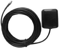 The GPS module receiver will track up to 16 satellites at a time while providing fast time-to-first-fix and 1Hz navigation updates. Its superior capability meets the sensitivity & accuracy requirements of car navigation as well as other location-based applications, such as AVL system. Handheld navigator, PDA, pocket PC, or any battery operated navigation system.
The module communicates with application system via RS232 (TTL level) with NMEA0183 protocol.
Main Features:
- Built-in high performance NMEX chipset.
- Average Cold Start in 60 seconds.
- Ultra Low power consumption.( SA3618 27mA typ @ 3.3V )
- 16 channels All-in-View tracking.
- On chip 4Mb flash memory.
- TTL level serial port for GPS receiver command message Interface.
- Compact Board Size
Technical Specifications:
- Electrical Characteristics
- General
Frequency L1, 1575.42 MHz
C/A code 1.023 MHz chip rate
Channels 16 - Sensitivity
Tracking -152dBm typ
Acquisition -139dBm typ - Accuracy
Position 5 meters CEP (90%) horizontal, SA off.
Velocity 0.1 meters/second
Time 1 microsecond synchronized to GPS time
- General
- Dynamic Conditions
Altitude 10,000 meters max
Horizontal Velocity 300 kilometers/hour max
Vertical Velocity 36 kilometers/hour max
Acceleration 2g, max
Jerk 4 meters/second3, max - Power
Main power input 3.3 ±5% VDC input.
Supply Current SA3618 26 mA @ 3.3V (Continuous mode) - Serial Port
Electrical interface one full duplex serial communication, TTL interface
Protocol message NMEA-0183, version 3.0 optional.
Default NMEA GGA, GSA, GSV, RMC and VTC. 9600 baud rate, 8 bits data, 1 start, 1 stop, no parity. - Recommended External Antenna Specification
Gain 20dB (including cable loss)
Noise figure 1.5dB
Current 3 ~ 30mA
Operate Voltage 2.5 ~ 2.8V
Serial Interface
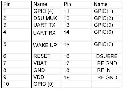
Communication to the SA3618 is provided via a serial interface. A 10-pin 1.27mm whole connector is used. Pin 6 (Reset) is the active-low reset input. The SA3618 always requires a reset at power-up, or it will not start properly. An optional onboard reset circuit can be provided. A reset forces the SA3618 processor to reboot, but will not influence other parameters such as hot or cold start. Pin 1 (GPIO [4]) and pin 10 (GPIO [0]) are spare pins that can be used e.g. to control power modes, to indicate SA3618 status, or to force a cold start. They can be left unconnected if desired.
I/O voltage level is set to 2.7V.
PIN DESCRIPTION OF SA3618
 GETTING GPS DATA:
After the GPS Module computes the positioning and other useful information, it then transmits the data in some standard format. With differential GPS signal input the accuracy ranges from 1 to 5 m; however, without differential input, the accuracy can be 25 m.
About 60 s after the GPS module is cold booted it begins to output a set of data (according to the NMEA format) though port C once every second at 9600 bps, 8 data bits, one stop bit, and no parity. NMEA GPS messages include six groups of data sets: GGA, GGL, GSA, GSV, RMC, and VTG. We use only the most useful RMC message- Recommended Minimum Specific GNSS Data-which contains all of the basic information required to build a navigation system.
We only need position and time data, so the UTC position, longitude with east west indicator, and latitude with north/south indicator are picked out from the RMC message. All of this data will be formatted into a standard fixed length packet with some other helpful information. Next, this data packet will be transmitted to the control center and stored in the micro controller.
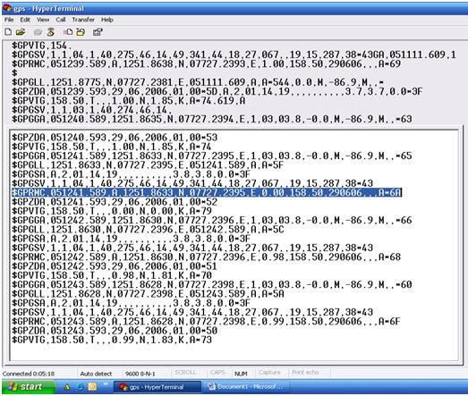
Here’s a sample of how the GPS receiver antenna receives information from the GPS satellite in NMEA format:
NMEA format sample:
The GPS module that we are using in this unit is SA3618 and the GPS receiving antenna used is G-501.
SA3618 NMEA Protocol
The SA3618 software is capable of supporting the following NMEA message
Formats:
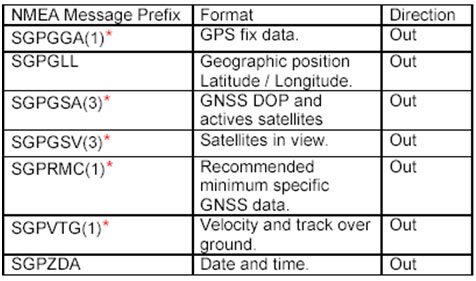 * (1): 1sec output 1msg, (3): 3sec output 1msg, 9600 baud rate (Standard output)
General NMEA Format:
The general NMEA (National Marine Electronics Association) format consists of an ASCII string commencing with a. $. Character and terminating with a <CR><LF> sequence. NMEA standard messages commence with .GP. then a 3-letter message identifier. NemeriX specific messages commence with $PNMRX followed by a 3 digit number. The message header is followed by a comma delimited list of fields optionally terminated with a checksum consisting of an asterix .*. and a 2 digit hex value representing the checksum. There is no comma preceding the checksum field. When present, the checksum is calculated as a bitwise exclusive of the characters between the. $. and.*.. As an ASCII representation, the number of digits in each number will vary depending on the number and precision, hence the record length will vary. Certain fields may be omitted if they are not used, in which case the field position is reserved using commas to ensure correct interpretation of subsequent fields. The tables below indicate the maximum and minimum widths of the fields to allow for buffer size allocation.
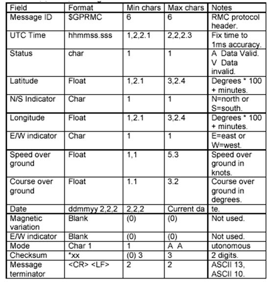
$GPRMC: This message transfers recommended minimum specific GNSS data. The $GPRMC message format is as shown below

how to compute for the distance using information from google earth? DMS