– Contents provided by www.pt.com
1. Overview
Signaling System No. 7 is a global standard for telecommunications defined by the International Telecommunication Union (ITU) Telecommunication Standardization Sector (ITU-T). The standard defines the procedures and protocol by which network elements in the public switched telephone network (PSTN) exchange information over a digital signaling network to effect wireless (cellular) and wire line call setup, routing and control. The ITU definition of SS7 allows for national variants such as North America’s American National Standards Institute (ANSI) and Bell Communications research (Telcordia Technologies) standards and Europe’s European Telecommunications Standards Institute (ETSI) standard.
The SS7 network and protocol are used for:
- Local number portability (LNP)
- Toll-free (800/888) and toll (900) wire line services
- Enhanced call features such as call forwarding, calling party name/number display and three-way calling.
- Efficient and secure worldwide telecommunications
- Basic call setup, management and tear down
- Wireless services such as personal communications services (PCS), wireless roaming and Mobile subscriber authentication
1.a Signaling Links
SS7 messages are exchanged between network elements over 56 or 64 kilobit per second (kbps) bidirectional channels called signaling links. Signaling occurs out-of-band on dedicated channels rather than in-band on voice channels. Compared to in-band signaling, out-of-band signaling provides:
- Faster call setup times (compared to in-band signaling using multi-frequency (MF)
signaling tones) - More efficient use of voice circuits
- Support for Intelligent Network (IN) services, which require signaling to network
elements without voice trunks (e.g., database systems) - Improved control over fraudulent network usage
1.b Signaling Points
Each signaling point in the SS7 network is uniquely identified by a numeric point code. Point codes are carried in signaling messages exchanged between signaling points to identify the source and destination of each message. Each signaling point uses a routing table to select the appropriate signaling path for each message.
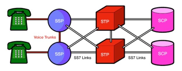
There are three kinds of signaling points in the SS7 network.
- SSP (Service Switching Point)
- STP (Signal Transfer Point)
- SCP (Service Control Point)

SSPs are switches that originate, terminate or tandem calls. An SSP sends signaling messages to other SSPs to setup, manage and release voice circuits required to complete a call. An SCP sends a response to the originating SSP containing the routing number(s) associated with the dialed number. An alternate routing number may be used by the SSP if the primary number is busy or the call is unanswered within a specified time. Actual call features vary from network to network and from service to service.
Network traffic between signaling points may be routed via a packet switch called an STP. An STP routes each incoming message to an outgoing signaling link based on routing information contained in the SS7 message. Because it acts as a network hub, an STP provides improved utilization of the SS7 network by eliminating the need for direct links between signaling points.
Links between signaling points are also provisioned in pairs. Traffic is shared across all links in the linkset. If one of the links fails, the signaling traffic is rerouted over another link in the linkset.
1.c SS7 Signaling Link Types
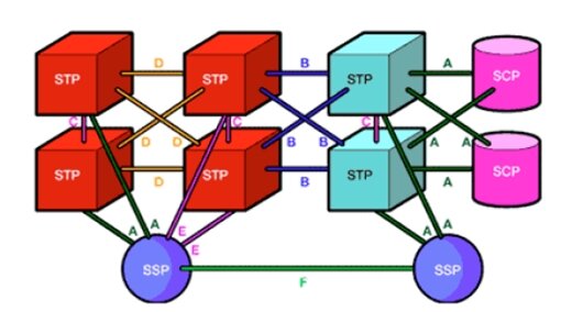
Signaling links are logically organized by link type (“A” through “F”) according to their use in the SS7
signaling network.
A Link: An “A” (access) link connects a signaling end point (e.g., an SCP or SSP) to an STP. Only
messages originating from or destined to the signaling end point are transmitted on an “A” link.
B Link: A “B” (bridge) link connects one STP to another. Typically, a quad of “B” links interconnect
peer (or primary) STP (e.g., the STPs from one network to the STPs of another network). The distinction between a “B” link and a “D” link is rather arbitrary. For this reason, such links may be referred to as “B/D” links.

C Link: A “C” (cross) link connects STPs performing identical functions into a mated pair. A “C” link is
used only when an STP has no other route available to a destination signaling point due to link failure(s). Note that SCPs may also be deployed in pairs to improve reliability; unlike STPs however, mated SCPs are not interconnected by signaling links.
D Link: A “D” (diagonal) link connects a secondary (e.g., local or regional) STP pair to a primary (e.g,
Inter-network gateway) STP pair in a quad-link configuration. Secondary STPs within the same network are connected via a quad of “D” links. The distinction between a “B” link and a “D” link is rather arbitrary. For this reason, such links may be referred to as “B/D” links.
E Link: An “E” (extended) link connects an SSP to an alternate STP. “E” links provide an alternate
signaling path if an SSP’s “home” STP cannot be reached via an “A” link. “E” links are not
usually provisioned unless the benefit of a marginally higher degree of reliability justifies the
added expense.
F Link: An “F” (fully associated) link connects two signaling end points (i.e., SSPs and SCPs). “F”
links are not usually used in networks with STPs. In networks without STPs, “F” links directly
connect signaling points.
2. SS7 Protocol Stack
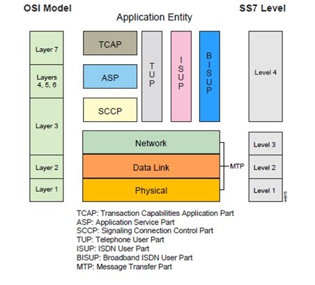
The hardware and software functions of the SS7 protocol are divided into functional abstractions called
“levels.” These levels map loosely to the Open Systems Interconnect (OSI) 7-layer model defined by
the International Standards Organization (ISO).

2.a Message Transfer Part
The Message Transfer Part (MTP) is divided into three levels.
The lowest level, MTP Level 1, is equivalent to the OSI Physical Layer. MTP Level 1 defines the physical, electrical and functional characteristics of the digital signaling link. Physical interfaces defined include E-1 (2048 kb/s; 32 64 kb/s channels), DS-1 (1544 kb/s; 24 64kb/s channels), V.35 (64 kb/s), DS-0 (64 kb/s) and DS-0A (56 kb/s).
MTP Level 2 ensures accurate end-to-end transmission of a message across a signaling link. Level 2 implements flow control, message sequence validation and error checking. When an error occurs on a signaling link, the message (or set of messages) is retransmitted. MTP Level 2 is equivalent to the OSI Data Link Layer
MTP Level 3 provides message routing between signaling points in the SS7 network. MTP Level 3 reroutes traffic away from failed links and signaling points and controls traffic when congestion occurs. MTP Level 3 is equivalent to the OSI Network Layer.
2.b ISDN User Part (ISUP)
The ISDN User Part (ISUP) defines the protocol used to set-up, manage and release trunk circuits that carry voice and data between terminating line exchanges (e.g., between a calling party and a called party). ISUP is used for both ISDN and non-ISDN calls. However, calls that originate and terminate at the same switch do not use ISUP signaling.
2.c Telephone User Part (TUP)
In some parts of the world, the Telephone User Part (TUP) is used to support basic call setup and tear-down. TUP handles analog circuits only. In many countries, ISUP has replaced TUP for call management.
2.d Signaling Connection Control Part (SCCP)
SCCP provides connectionless and connection-oriented network services and global title translation (GTT) capabilities above MTP Level 3. A global title is an address (e.g., a dialed 800 number, calling card number or mobile subscriber identification number) that is translated by SCCP into a destination point code and subsystem number. A subsystem number uniquely identifies an application at the destination signaling point. SCCP is used as the transport layer for TCAP-based services.
2.e Transaction Capabilities Applications Part (TCAP)
TCAP supports the exchange of non-circuit related data between applications across the SS7 network using the SCCP connectionless service. Queries and responses sent between SSPs and SCPs are carried in TCAP messages.
