Taking a reverse on your car is difficult when there are no sensors. Here is a simple circuit that will protect your vehicle from damage while taking a reverse. There will be an alarm when the car gets too close to a wall or an object and needs to be stopped.
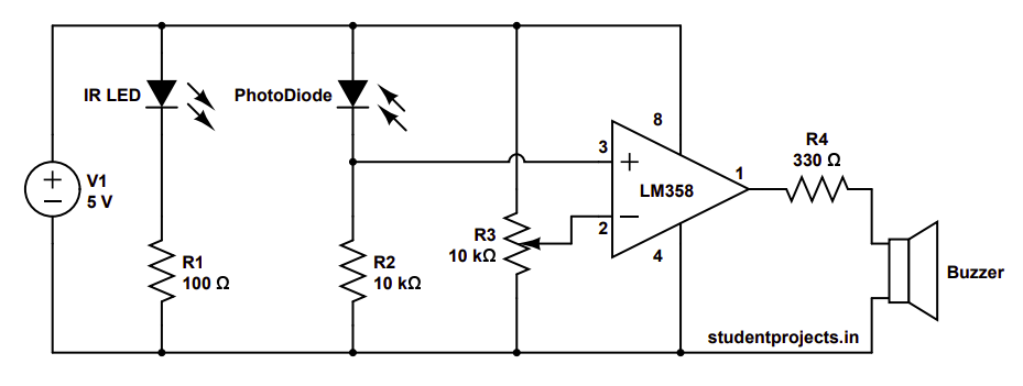
Here is the circuit diagram.
This car parking sensor circuit is simple to build and only requires a few components, which are mentioned below.
IR LED
An IR LED (infrared light-emitting diode) is a special-purpose LED that emits infrared rays with wavelengths ranging from 700 nm to 1 mm. So it is invisible to human eyes. IR LEDs are more commonly used in security systems and remote control devices.
Photodiode
A photodiode is a semiconductor device with a P-N junction that converts light into an electrical current. The resistance and output voltage of the photodiode alter in response to the amount of infrared light received.
LM358
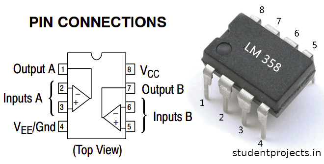
The LM358 is an operational amplifier (Op-Amp), and it is used as a voltage comparator in this design. The LM358 contains two independent voltage comparators. We have used only one comparator, with inputs at PINs 2 and 3 and outputs at PIN 1. The voltage comparator has two inputs: one inverting and the other non-inverting (PIN 2 and 3). The output of the comparator (PIN 1) is High when the voltage at the non-inverting input (+) is greater than the voltage at the inverting input (-). If the inverting input (-) has a higher voltage than the non-inverting end (+), the output is LOW.
Working of an IR Sensor
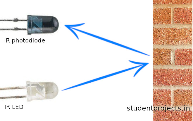
An IR LED serves as the emitter, while an IR photodiode serves as the detector. An IR LED emits infrared light, which is detected by the IR photodiode. The resistance and output voltage of the photodiode alter in response to the amount of infrared light received. The IR sensor’s basic functioning concept is shown below.
How does the Reverse Car Parking Sensor circuit work?
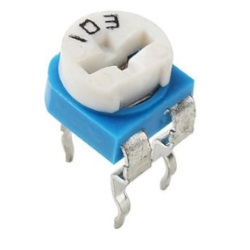
As per the circuit diagram given above, a variable resistor is connected to inverting end of LM358(Pin 2) to adjust the sensitivity of the sensor. A junction of the photodiode and a resistor is connected to the non-inverting end of LM358(Pin 3).
When the circuit is switched ON and when there is no object near the IR LED and photodiode, then there will be no IR radiation towards the photodiode. Hence the voltage across series resistor R2 decreases. Non-inverting end (pin 3) gets less voltage when compared to inverting end (pin2). Hence the output becomes LOW and the LED turns OFF.
Now when there is an object near the IR LED and photodiode, the photodiode absorbs the IR generated by the IR LED after it is reflected by the object. When reflected IR hits the photodiode, the voltage across it drops, while the voltage across the series resistor R2 increases. Non-inverting end (pin 3) gets high voltage when compared to inverting end (pin2). Hence the output becomes HIGH and the LED turns ON.
Inverting end of LM358 is connected to the 10k pot. Make the necessary adjustments to ensure that voltage comparison works properly.
So, give it a shot and let me know if you have any questions in the comments section below. I’ll be happy to assist you!
