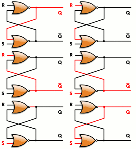
A flip-flop or latch is a circuit that has two stable states and can be used to store state information. The circuit can be made to change state by signals applied to one or more control inputs and will have one or two outputs. It is the basic storage element in sequential logic. Flip-flops and latches are a fundamental building block of digital electronics systems used in computers, communications, and many other types of systems.
When using static gates as building blocks, the most fundamental latch is the simple SR latch, where S and R stand for set and reset. It can be constructed from a pair of cross-coupled NOR logic gates. The stored bit is present on the output marked Q.
While the S and R inputs are both low, feedback maintains the Q and Q outputs in a constant state, with Q the complement of Q. If S (Set) is pulsed high while R (Reset) is held low, then the Q output is forced high, and stays high when S returns to low; similarly, if R is pulsed high while S is held low, then the Q output is forced low, and stays low when R returns to low.

1 2 3 4 5 6 7 8 9 10 11 12 13 14 15 16 17 18 19 | module srff(q,q1,r,s,clk); output q,q1; input r,s,clk; reg q,q1; initial begin q=1'b0; q1=1'b1; end always @(posedge clk) begin case({s,r}) {1'b0,1'b0}: begin q=q; q1=q1; end {1'b0,1'b1}: begin q=1'b0; q1=1'b1; end {1'b1,1'b0}: begin q=1'b1; q1=1'b0; end {1'b1,1'b1}: begin q=1'bx; q=1'bx; end endcase end endmodule |

Chutiya hain kya?