The present concept implements controlling of pump which pumps water from the sump (underground tank) to the overhead tank, using 8951 microcontroller.
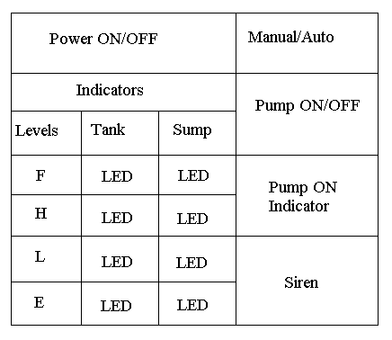
The control panel, i.e. the main control unit of the system which consists of the primary control switches, pump indicator, siren and level indicators. The visual example of how switches And the indicators can be placed as shown the figure below.

In the figure shown above there are total of nine LEDs, four of which indicates the water level in the tank, another four indicates the water level in the sump and one LED indicates whether the pump is ON/OFF. It also consists of three switches.
- Switch 1 is the main power switch which is used to activate the system.
- Switch 2 is used to select whether to operate the pump in AUTO or MANUAL mode.
- Switch 3 comes to picture only when the system is operated in MANUAL mode. It controls the direct activation of the pump.
Description :
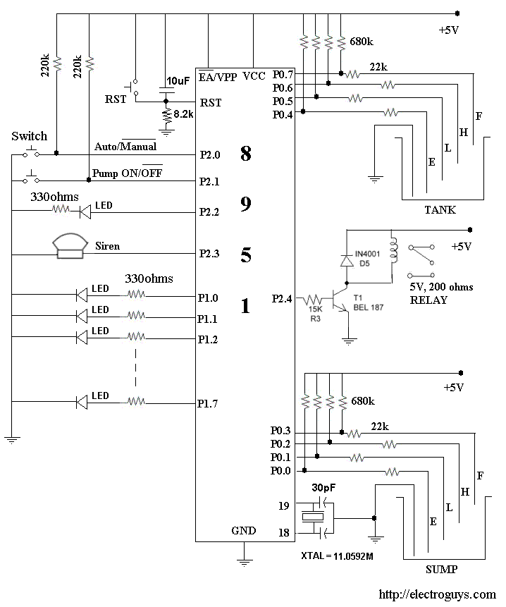
This system is built around an 8951 microcontroller and the circuit diagram is as given below.

As you can see in the above diagram, port 0 is exclusively used as an input port which takes the information regarding the water level in the sump as well as in the overhead tank.
Port 1 is used as output port which is connected to the indicator that indicates the water level in both the tanks.
Port 2 is used as in/out port, it takes the input from switch 2 and switch 3 and gives the output which is connected to pump indicator, siren and the relay which controls the switching of the pump.
Working of the system:
There are two modes of working for the system
- Manual mode
- Auto mode
Which is controlled by switch 2 (refer control panel diagram)
Manual mode:
When the system is active and in manual mode, it only indicates the water levels in the tanks and it doesn’t control any working of the pump. To activate the pump in manual mode switch 3 is used.
In this mode the operator should manually control the working of the pump. As in case if the tank is full, operator should switch of the pump which is not the case when compared to auto mode.
Auto mode:
When the system is active and in auto mode, it only indicates the water levels in the tanks and it controls the working of the pump.

Please give me program & hex code for water level indicator cum controller using 8951 microcontroller
I’m very much interested in it. Can u give me the source code(Hex file)please?
My mail add-solangi01@yahoo.com
even i would like to have some more information on your project. please
I am interested in this project and I would like more information,
thank you very much
hey can u plz send me the source code(hex file) 4 these project ?
hi
hi me too.. can i have the source code too, please? =) (hex file) very much
appreciated
thanks! xer_nuj123@yahoo.com
i want to ask something. Ic micro c and pic can use the same program to
control water level?
Hey..!! I am interested in this project. Can u send me a source code(Hex code) for this project?)
Hey..!! I am interested in this project. Can u send me a source code(Hex code) for this project?)
this is my mail address: ritsnec41@gmail.com
hi,nice project cud u pls send me d source code, pcb diagram , components required
& detail working of it.
mail me on-laddoo4uall@gmail.com
hi,nice project, cud U pls send me d source code, PCB diagram , components required
& detail working of it.
mail me on-laddoo4uall@gmail.com
this is better than other one can u pls send me the complete circuit diagram
and the source code. thankyou
pls send me the source code, pcb diagram , components required
& detail working of it.
one more in the que,i have made the project but its not working, it will be great if u can send the details along with the source code or any means through which I can get help
I’m very much interested in it. Can u give me the source code(Hex file)please?
your project is really good ,but i need it to be interfaced with 8086
and please forward it to noor@iiitdm.ac.in,,reply asap
sir can u mail me the c program of the project please
ashim30@gmail.com
Hi…Iam interested to do this project.pls forward the circuit descpription indetail
n the hex file to my email
Pl send me the Program for PIC 8951 for water level indicator cum controller Thanks in advance pl send to menonps@hotmail.com
I am working on a “Water Level Controller” project. I need to know that which type of motor is required and of how much volt? And for water level sensing , which sensor i should use?
I’m very much interested in it. Can u give me the source code(Hex file)please
sir please give me hex code this water level control.I want to use this
at home,
I’m very much interested in it. Can u give me the source code(Hex file)please
sir i’m btech final year student. my project is water level indicater.
please help me to generate the source code for this project….
sir i’m btech final year student. my project is water level indicater.
please help me to generate the source code for this project…
Hey can u please give me entire description s well as code?
my email id is : aashitairani@yahoo.co.in
Very nice project.I’m looking forward to make the project.
Can u pls mail me the source code?
Interesting project, I will be intersested to have source /hex code
can i get it throug mail anandkulkarni.s@gmail.com
thank u
can you give hex code water level control.
please can u give me hex code of water level control.My e-mail is
tanveerhussainshah@rocketmail.com.
salam…sir i am also doing this project can you please send me programminh in c++
my email is ahtisham_uet@yahoo.com
sir please give me hex code this water level control.I want to use this
at home,
sir i want to do project based on this so please giv me the hex code of tis
water level controller
Please sir give me the details of this project. It relates to my final year project. email: oladejoshuaib@yahoo.com
Those resistors inside Sump and Tank would they be made to enter water inside. Please reply and give details.
Sir,
this is P.Brahma Teja please send the complete program code n how to dup it into controller and provide me relavant information about this project with neat block digram & description please sir its very urgent…..
Can u pls mail me the source code? >> rafadhel88@liverpoolfc.net
i want source code
can you please sed me the source code of the project.
Email: nblfire@hotmail.com
can u pl send me entire code
veerapandu2004@yahoo.co.in
can you please sed me the source code of the project.
my email- vu2sto@gmail.com
hi “iam looking for a technology where i can activate a moter using my mobile using SMS and turn off using SMS or i will use the water level indicator ”
is the any way anyone can provide me a soluton for this
eg:iam in chennai & my agriculture land is in coimbatore,iam willing to have maintain my aggriculture sitting from my office
sir i want to do mini project on this. can u give me abstract,block diag
ram,circuit diagram
Please give me program & hex code for water level indicator cum controller using 8951 microcontroller
thanks
hi sir have goan through the comments about water level controller cum indicator finding to understand the code programe . have got the ic 89c51 from market and constucted the ckt provided above but unable to understand the operation does it require programing and wat about power supply does it require 3 power supply of 5v each and for siren speaker is ok
Yo do anybody know a site to watch Free without sign ups?
it imp to day to day life
Hello, I am New.
Thank you for your forum, I will do my best to participate here but know that I’m shy.
Please give me program code for water level indicator cum controller using 8951 microcontroller
axplain@yahoo.com