RS (REGISTER SELECT):
There are two important registers inside the LCD. When RS is low (0), the data is to be treated as a command or special instruction (such as clear screen, position cursor, etc.). When RS is high (1), the data that is sent is a text data which should be displayed on the screen. For example, to display the letter “T” on the screen you would set RS high.
RW (READ/WRITE):
The RW line is the “Read/Write” control line. When RW is low (0), the information on the data bus is being written to the LCD. When RW is high (1), the program is effectively querying (or reading) the LCD. Only one instruction (“Get LCD status”) is a read command. All others are write commands, so RW will almost be low.
EN (ENABLE):
The EN line is called “Enable”. This control line is used to tell the LCD that you are sending it data. To send data to the LCD, your program should first set this line high (1) and then set the other two control lines and/or put data on the data bus. When the other lines are completely ready, bring EN low (0) again. The 1-0 transition tells the 44780 to take the data currently found on the other control lines and on the data bus and to treat it as a command.
D0-D7 (DATA LINES):
The 8-bit data pins, D0-D7 are used to send information to the LCD or read the content of the LCD’s internal registers.
To display letters and numbers, we send ASCII codes for the letters A-Z, a-z and numbers 0-9 to these pins while making RS=1.
There are also instruction command codes that can be sent to the LCD to clear the display or force the cursor to the home position or blink the cursor.
We also use RS=0 to check the busy flag bit to see if the LCD is ready to receive the information. The busy flag is D7 and can be read when R/W = 1 and RS=0, as follows: if R/W = 1, RS = 0. When D7=1 (busy flag = 1), the LCD is busy taking care of internal operations and will not accept any new information. When D7 = 0, the LCD is ready to receive new information.
Note: it is recommended to check the flag before writing any data to LCD.
LCD COMMAND CODES:
| CODE (HEX) | COMMAND TO LCD INSTRUCTION REGISTER |
| 0X01 | CLEAR DISPLAY SCREEN |
| 0X02 | RETURN HOME |
| 0X04 | DECREMENT CURSOR(SHIFT CURSOR TO LEFT) |
| 0X06 | INCREMENT CURSOR(SHIFT CURSOR TO RIGHT) |
| 0X05 | SHIFT DISPLAY RIGHT |
| 0X07 | SHIFT DISPLAY LEFT |
| 0X08 | DISPLAY OFF,CURSOR OFF |
| 0X0A | DISPLAY OFF,CURSOR ON |
| 0X0C | DISPLAY ON,CURSOR OFF |
| 0X0E | DISPLAY ON CURSOR BLINKING |
| 0X0F | DISPLAY ON CURSOR BLINKING |
| 0X10 | SHIFT CURSOR POSITION TO LEFT |
| 0X14 | SHIFT CURSOR POSITION TO RIGHT |
| 0X18 | SHIFT THE ENTIRE DISPLAY TO THE LEFT |
| 0X1C | SHIFT THE ENTIRE DISPLAY TO THE RIGHT |
| 0X80 | FORCE CURSOR TO BEGINNING OF 1ST LINE |
| 0XC0 | FORCE CURSOR TO BEGINNING OF 2ND LINE |
| 0X38
0X30 0X28 0X20 |
8-BIT INTERFACE, 2 LINES, 5*7 PIXELS
8-BIT INTERFACE, 1 LINE, 5*7 PIXELS 4-BIT INTERFACE, 2 LINES, 5*7 PIXELS 4-BIT INTERFACE, 1 LINE, 5*7 PIXELS |
CURSOR ADDRESSES FOR LCD’S:
| 16×2 LCD 80 81 82 83 84 85 86 through 8F
C0 C1 C2 C3 C4 C5 C6 through CF |
| 20×1 LCD 80 81 82 83 through 93 |
| 20×2 LCD 80 81 82 83 through 93
C0 C1 C2 C3 through D3 |
| 20×4 LCD 80 81 82 83 through 93
C0 C1 C2 C3 through D3 94 95 96 97 through A7 D4 D5 D6 D7 through E7 |
| 40×2 LCD 80 81 82 83 through A7
C0 C1 C2 C3 through E7 |
| NOTE: All data is in HEX. |
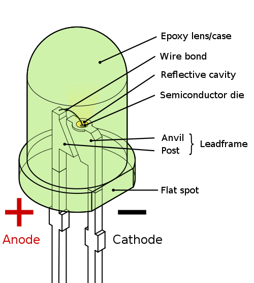
LIGHT EMITTING DIODE:
A light-emitting diode (LED) is a semiconductor diode that emits incoherent narrow spectrum light when electrically biased in the forward direction of the pn-junction, as in the common LED circuit. This effect is a form of electroluminescence.
KIEL SOFTWARE:
Many companies provide the 8051 assembler, some of them provide shareware version of their product on the Web, Kiel is one of them. We can download them from their Websites. However, the size of code for these shareware versions is limited and we have to consider which assembler is suitable for our application.
KIEL U VISION2
This is an IDE (Integrated Development Environment) that helps you write, compile, and debug embedded programs. It encapsulates the following components:
- A project manager
- A make facility
- Tool configuration
- Editor
- A powerful debugger
To get start here are some several example programs
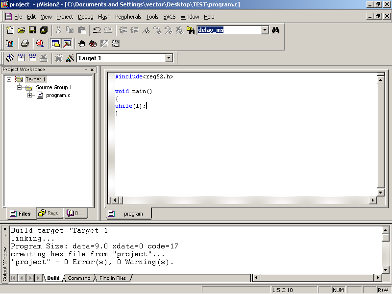
BUILDING AN APPLICATION IN UVISION2:
To build (compile, assemble, and link) an application in uVision2, you must:
- Select Project–Open Project
(For example, \C166\EXAMPLES\HELLO\HELLO.UV2)
- Select Project – Rebuild all target files or Build target. UVision2 compiles, assembles, and links the files in your project.
CREATING YOUR OWN APPLICATION IN UVISION2:
To create a new project in uVision2, you must:
- Select Project – New Project.
- Select a directory and enter the name of the project file.
- Select Project – Select Device and select an 8051, 251, or C16x/ST10 device from the Device
- Database
- Create source files to add to the project.
- Select Project – Targets, Groups, and Files. Add/Files, select Source Group1, and add the source files to the project.
- Select Project – Options and set the tool options. Note when you select the target device from the Device Database all-special options are set automatically. You only need to configure the memory map of your target hardware. Default memory model settings are optimal for most.
your project is cool but mine is better..
…….
Sir can send me the codes used in this project? rjaylui@yahoo.com! Thanks a lot!
Sir can you send me the codes used in this project? rjaylui@yahoo.com! Thanks a lot!
The source code shows error when compiling pls help
pls send me the code
uthmanjta@gmail.com
the source code contains somany error. dont waste ur time in this project. i request the author pls post the correct code and hex.
but no answer from the autor and admin?????????????????????????????????????????/
send me this code sir……
SIR I READ THIS PROJECT ITS NICE …… PLEASE, CAN U SEND SOURCE CODE TO MY MAILID rk_yadav1@yahoo.com
i need the god damn code of pc operation control using ir remote
If u want embedded project pls contact me. (with report&program). Unaiskavot1@gmail.com