THE RECEIVER:
Many different receiver circuits exist on the market. The most important selection criteria are the modulation frequency used and the availability in you region.

In the picture above you can see a typical block diagram of such an IR receiver. Don’t be alarmed if you don’t understand this part of the description, for everything is built into one single electronic component.
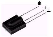
The received IR signal is picked up by the IR detection diode on the left side of the diagram. This signal is amplified and limited by the first 2 stages. The limiter acts as an AGC circuit to get a constant pulse level, regardless of the distance to the handset.
As you can see only the AC signal is sent to the Band Pass Filter. The Band Pass Filter is tuned to the modulation frequency of the handset unit. Common frequencies range from 30 kHz to 60 kHz in consumer electronics.
The next stages are a detector, integrator and comparator. The purpose of these three blocks is to detect the presence of the modulation frequency. If this modulation frequency is present the output of the comparator will be pulled low.
As I said before, all these blocks are integrated into a single electronic component. There are many different manufacturers of these components on the market. And most devices are available in several versions each of which are tuned to a particular modulation frequency.
Please note that the amplifier is set to a very high gain. Therefore the system tends to start oscillating very easily. Placing a large capacitor of at least 22µF close to the receiver’s power connections is mandatory to decouple the power lines. Some data sheets recommend a resistor of 330 Ohms in series with the power supply to further decouple the power supply from the rest of the circuit.
There are several manufacturers of IR receivers on the market. Siemens, Vishay and Telefunken are the main suppliers here in Europe. Siemens has its SFH506-xx series, where xx denotes the modulation frequency of 30, 33, 36, 38, 40 or 56 kHz. Telefunken had its TFMS5xx0 and TK18xx series, where xx again indicates the modulation frequency the device is tuned to. It appears that these parts have now become obsolete. They are replaced by the Vishay TSOP12xx, TSOP48xx and TSOP62xx product series.
Sharp, Xiamen Hualian and Japanese Electric are 3 Asian IR receiver producing companies. Sharp has devices with very cryptic ID names, like: GP1UD26xK, GP1UD27xK and GP1UD28xK, where x is related to the modulation frequency. Hualian has its HRMxx00 series, like the HRM3700 and HRM3800. Japanese Electric has a series of devices that don’t include the modulation frequency in the part’s ID. The PIC-12042LM is tuned to 36.7 kHz, and the PIC12043LM is tuned to 37.9 kHz.
LIQUID CRYSTAL DISPLAY:
A liquid crystal display (LCD) is a thin, flat panel used for electronically displaying information such as text, images, and moving pictures. Its uses include monitors for computers, televisions, instrument panels, and other devices ranging from aircraft cockpit displays, to every-day consumer devices such as video players, gaming devices, clocks, watches, calculators, and telephones. Among its major features are its lightweight construction, its portability, and its ability to be produced in much larger screen sizes than are practical for the construction of cathode ray tube (CRT) display technology. Its low electrical power consumption enables it to be used in battery-powered electronic equipment. It is an electronically-modulated optical device made up of any number of pixels filled with liquid crystals and arrayed in front of a light source (backlight) or reflector to produce images in color or monochrome. The earliest discovery leading to the development of LCD technology, the discovery of liquid crystals, dates from 1888. By 2008, worldwide sales of televisions with LCD screens had surpassed the sale of CRT units.
PIN DESCRIPTION:
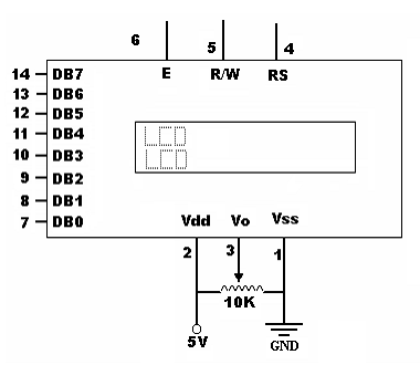
| PIN | SYMBOL | I/O | DESCRIPTION |
| 1 | VSS | — | Ground |
| 2 | VCC | — | +5V power supply |
| 3 | VEE | — | Power supply to control contrast |
| 4 | RS | I | RS=0 to select command register
RS=1 to select data register |
| 5 | R/W | I | R/W=0 for write
R/W=1 for read |
| 6 | EN | I/O | Enable |
| 7 | DB0 | I/O | The 8-bit data bus |
| 8 | DB1 | I/O | The 8-bit data bus |
| 9 | DB2 | I/O | The 8-bit data bus |
| 10 | DB3 | I/O | The 8-bit data bus |
| 11 | DB4 | I/O | The 8-bit data bus |
| 12 | DB5 | I/O | The 8-bit data bus |
| 13 | DB6 | I/O | The 8-bit data bus |
| 14 | DB7 | I/O | The 8-bit data bus |
VCC, VSS and VEE:
While VCC and VSS provide +5V and ground respectively, VEE is used for controlling LCD contrast.
your project is cool but mine is better..
…….
Sir can send me the codes used in this project? rjaylui@yahoo.com! Thanks a lot!
Sir can you send me the codes used in this project? rjaylui@yahoo.com! Thanks a lot!
The source code shows error when compiling pls help
pls send me the code
uthmanjta@gmail.com
the source code contains somany error. dont waste ur time in this project. i request the author pls post the correct code and hex.
but no answer from the autor and admin?????????????????????????????????????????/
send me this code sir……
SIR I READ THIS PROJECT ITS NICE …… PLEASE, CAN U SEND SOURCE CODE TO MY MAILID rk_yadav1@yahoo.com
i need the god damn code of pc operation control using ir remote
If u want embedded project pls contact me. (with report&program). Unaiskavot1@gmail.com