USER INTERFACES:
Interface designers at PARC, Apple Computer, Boeing and HP minimize the number of types of user actions. For example, use two buttons (the absolute minimum) to control a menu system (just to be clear, one button should be “next menu entry” the other button should be “select this menu entry”). A touch-screen or screen-edge buttons also minimize the types of user actions.
Another basic trick is to minimize and simplify the type of output. Designs should consider using a status light for each interface plug, or failure condition, to tell what failed. A cheap variation is to have two light bars with a printed matrix of errors that they select- the user can glue on the labels for the language that she speaks.
For example, Boeing’s standard test interface is a button and some lights. When you press the button, all the lights turn on. When you release the button, the lights with failures stay on. The labels are in Basic English.
Designers use colors. Red defines the users can get hurt- think of blood. Yellow defines something might be wrong. Green defines everything’s OK.
Another essential trick is to make any modes absolutely clear on the user’s display. If an interface has modes, they must be reversible in an obvious way. Most designers prefer the display to respond to the user. The display should change immediately after a user action. If the machine is going to do anything, it should start within 7 seconds, or give progress reports.
One of the most successful general-purpose screen-based interfaces is the two menu buttons and a line of text in the user’s native language. It’s used in pagers, medium-priced printers, network switches, and other medium-priced situations that require complex behavior from users. When there’s text, there are languages. The default language should be the one most widely understood.
MICROCONTROLLERS
Microcontrollers as the name suggests are small controllers. They are like single chip computers that are often embedded into other systems to function as processing/controlling unit. For example the remote control you are using probably has microcontrollers inside that do decoding and other controlling functions. They are also used in automobiles, washing machines, microwave ovens, toys … etc, where automation is needed.
Micro-controllers are useful to the extent that they communicate with other devices, such as sensors, motors, switches, keypads, displays, memory and even other micro-controllers. Many interface methods have been developed over the years to solve the complex problem of balancing circuit design criteria such as features, cost, size, weight, power consumption, reliability, availability, manufacturability. Many microcontroller designs typically mix multiple interfacing methods. In a very simplistic form, a micro-controller system can be viewed as a system that reads from (monitors) inputs, performs processing and writes to (controls) outputs.
Embedded system means the processor is embedded into the required application. An embedded product uses a microprocessor or microcontroller to do one task only. In an embedded system, there is only one application software that is typically burned into ROM. Example: printer, keyboard, video game player
Microprocessor – A single chip that contains the CPU or most of the computer
Microcontroller – A single chip used to control other devices
Microcontroller differs from a microprocessor in many ways. First and the most important is its functionality. In order for a microprocessor to be used, other components such as memory, or components for receiving and sending data must be added to it. In short that means that microprocessor is the very heart of the computer. On the other hand, microcontroller is designed to be all of that in one. No other external components are needed for its application because all necessary peripherals are already built into it. Thus, we save the time and space needed to construct devices.
MICROPROCESSOR VS MICROCONTROLLER:
Microprocessor:
- CPU is stand-alone, RAM, ROM, I/O, timer are separate
- Designer can decide on the amount of ROM, RAM and I/O ports.
- expensive
- versatility general-purpose
Microcontroller:
- CPU, RAM, ROM, I/O and timer are all on a single chip
- fix amount of on-chip ROM, RAM, I/O ports
- for applications in which cost, power and space are critical
- single-purpose
IR COMMUNICATION:
IR (infrared radiation) is the region of the electromagnetic spectrum between microwaves and visible light. In infrared communication an LED transmits the infrared signal as bursts of non-visible light. At the receiving end a photodiode or photoreceptor detects and captures the light pulses, which are then processed to retrieve the information they contain.
Wireless communication, as the term implies, allows information to be exchanged between two devices without the use of wire or cable. A wireless keyboard sends information to the computer without the use of a keyboard cable; a cellular telephone sends information to another telephone without the use of a telephone cable. Changing television channels, opening and closing a garage door, and transferring a file from one computer to another can all be accomplished using wireless technology. In all such cases, information is being transmitted and received using electromagnetic energy, also referred to as electromagnetic radiation. One of the most familiar sources of electromagnetic radiation is the sun; other common sources include TV and radio signals, light bulbs and microwaves. To provide background information in understanding wireless technology, the electromagnetic spectrum is first presented and some basic terminology defined.
The cheapest way to remotely control a device within a visible range is via Infra-Red light. Almost all audio and video equipment can be controlled this way nowadays. Due to this wide spread use the required components are quite cheap, thus making it ideal for us hobbyists to use IR control for our own projects.
This part of my knowledge base will explain the theory of operation of IR remote control, and some of the protocols that are in use in consumer electronics.
Infra-Red actually is normal light with a particular colour. We humans can’t see this color because its wave length of 950nm is below the visible spectrum. That’s one of the reasons why IR is chosen for remote control purposes, we want to use it but we’re not interested in seeing it. Another reason is because IR LED’s are quite easy to make, and therefore can be very cheap.
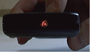
Although we humans can’t see the Infra-Red light emitted from a remote control doesn’t mean we can’t make it visible. A video camera or digital photo camera can “see” the Infra-Red light as you can see in this picture. If you own a web cam you’re in luck, point your remote to it, press any button and you’ll see the LED flicker.
Unfortunately for us there are many more sources of Infra-Red light. The sun is the brightest source of all, but there are many others, like: light bulbs, candles, central heating system, and even our body radiate Infra-Red light. In fact everything that radiates heat also radiates Infra-Red light.
Therefore we have to take some precautions to guarantee that our IR message gets across to the receiver without errors.
MODULATION:
Modulation is the answer to make our signal stand out above the noise. With modulation we make the IR light source blink in a particular frequency. The IR receiver will be tuned to that frequency, so it can ignore everything else.
You can think of this blinking as attracting the receiver’s attention. We humans also notice the blinking of yellow lights at construction sites instantly, even in bright daylight.
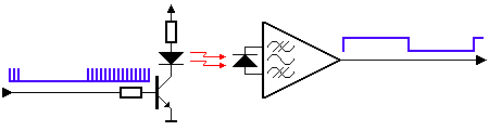
In the picture above you can see a modulated signal driving the IR LED of the transmitter on the left side. The detected signal is coming out of the receiver at the other side.
In serial communication we usually speak of ‘marks’ and ‘spaces’. The ‘space’ is the default signal, which is the off state in the transmitter case. No light is emitted during the ‘space’ state. During the ‘mark’ state of the signal the IR light is pulsed on and off at a particular frequency. Frequencies between 30 kHz and 60 kHz are commonly used in consumer electronics.
At the receiver side a ‘space’ is represented by a high level of the receiver’s output. A ‘mark’ is then automatically represented by a low level.
Please note that the ‘marks’ and ‘spaces’ are not the 1-s and 0-s we want to transmit. The real relationship between the ‘marks’ and ‘spaces’ and the 1-s and 0-s depends on the protocol that’s being used. More information about that can be found on the pages that describe the protocols.
THE TRANSMITTER:
The transmitter usually is a battery powered handset. It should consume as little power as possible, and the IR signal should also be as strong as possible to achieve an acceptable control distance. Preferably it should be shock proof as well.
Many chips are designed to be used as IR transmitters. The older chips were dedicated to only one of the many protocols that were invented. Nowadays very low power microcontrollers are used in IR transmitters for the simple reason that they are more flexible in their use. When no button is pressed they are in a very low power sleep mode, in which hardly any current is consumed. The processor wakes up to transmit the appropriate IR command only when a key is pressed.
Quartz crystals are seldom used in such handsets. They are very fragile and tend to break easily when the handset is dropped. Ceramic resonators are much more suitable here, because they can withstand larger physical shocks. The fact that they are a little less accurate is not important.
The current through the LED (or LED’s) can vary from 100mA to well over 1A! In order to get an acceptable control distance the LED currents have to be as high as possible. A trade-off should be made between LED parameters, battery lifetime and maximum control distance. LED currents can be that high because the pulses driving the LED’s are very short. Average power dissipation of the LED should not exceed the maximum value though. You should also see to it that the maximum peek current for the LED is not exceeded. All these parameters can be found in the LED’s data sheet.
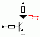
A simple transistor circuit can be used to drive the LED. A transistor with a suitable HFE and switching speed should be selected for this purpose.
The resistor values can simply be calculated using Ohm’s law. Remember that the nominal voltage drop over an IR LED is approximately 1.1V.
The normal driver, described above, has one disadvantage. As the battery voltage drops, the current through the LED will decrease as well. This will result in a shorter control distance that can be covered.
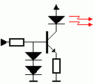
An emitter follower circuit can avoid this. The 2 diodes in series will limit the pulses on the base of the transistor to 1.2V. The base-emitter voltage of the transistor subtracts 0.6V from that, resulting in constant amplitude of 0.6V at the emitter. This constant amplitude across a constant resistor results in current pulses of a constant magnitude. Calculating the current through the LED is simply applying Ohm’s law again.
your project is cool but mine is better..
…….
Sir can send me the codes used in this project? rjaylui@yahoo.com! Thanks a lot!
Sir can you send me the codes used in this project? rjaylui@yahoo.com! Thanks a lot!
The source code shows error when compiling pls help
pls send me the code
uthmanjta@gmail.com
the source code contains somany error. dont waste ur time in this project. i request the author pls post the correct code and hex.
but no answer from the autor and admin?????????????????????????????????????????/
send me this code sir……
SIR I READ THIS PROJECT ITS NICE …… PLEASE, CAN U SEND SOURCE CODE TO MY MAILID rk_yadav1@yahoo.com
i need the god damn code of pc operation control using ir remote
If u want embedded project pls contact me. (with report&program). Unaiskavot1@gmail.com