Adjustable timer unit
There is a variety of outdoor light controllers available. Some switch lights ON at the fall of dusk and OFF at the break of dawn. Others switch lights ON at the end of dusk and OFF after few hours. But for domestic use, where we require light in the early morning also, these do not serve the purpose. The circuit described here solves this problem.
It offers the following features:
- It switches ON lights at about 6.00 PM and switches OFF at about 11.00 PM. Again it switches ON lights at about 4.30 AM and switches OFF about 6.00 AM. We can change this time by changing simple components.
- There are separate ON and OFF switches for easy operation of the system.
- It use LED indicators to detect different conditions of the circuit.
- Preset control to set the trigger time.
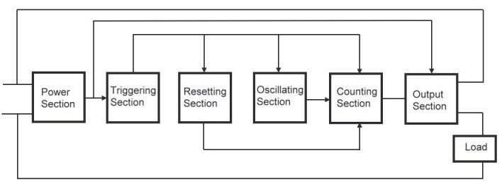
- The circuit comprises five sections.

1. Triggering
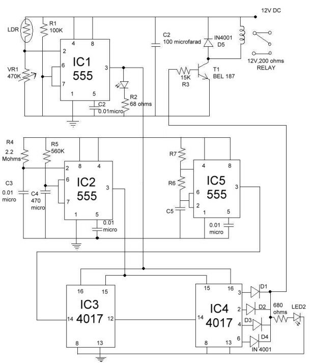
This section is used to trigger the circuit at the fall of dusk. It is configured around IC 1, which is working in the monostable mode. A variable voltage is fed to trigger pin 2 of IC 1 via LDR and VR 1. In the monostable mode of operation, the output of IC 1 stays high as long as its trigger input stays bellow 1/3 Vcc.
At night, the resistance of LDR is high, so the voltage at pin 2 is at a low level and hence the output of IC 1 goes high at night. The output condition of IC 1 can be detected from LED 1. the output of IC 1 gives power supply to the next stage.
2. Resetting
The next section is used to reset two 4017 decade counter ICs used in the counter section. This is also based on a 555 timer [IC 2]. Its trigger pin 2 is connected to capacitor C3 and resistor R4. In the absence of supply, there is no voltage across capacitor is bellow 1/3 Vcc and its output goes to a high state. The voltage across capacitor C3 increases, so that the voltage at pin 2 crosses 1/3 Vcc. The time period for which the output stays in the high state depends upon resistor R5 and capacitor C4 and is given by the relationship 1.1*R5*C4.
The output of IC 2 is given to the reset pin 15 of decade counter IC 3 and IC 4. These ICs are reset when IC 2 is triggered, and as long as the output of IC 3 is in the high state, the counters sty in the reset position.
3. Oscillator
This section is used to produce a square wave output. It is based on IC 5 an NE 555. Its output frequency depends upon resistors R6 and R7 and capacitor C5 and is calculated by the equation
1.443/( (R7+2R6)C5)
The output frequency is fed to the counter section.
4. Counting
The counter section is used to count the output frequency from the oscillating section. It uses two CMOS CD4017 ICs. The frequency from oscillating section, IC 5, is fed to the input pin of IC 3. IC 3 works as frequency divider and its output is fed to the input pin of IC 4.
The four outputs of IC 4 are combined by using diodes D1 through D4. This combined output is given to the last section. If any of the output is high, then the load is ON state. The condition of this combined output is detected by LED 2.
5. Output
The output section is used to switch the relay ON and OFF. It is based on BEL 187 transistor. The relay is connected at the collector of transistor. Diode D5 is connected to protect transistor. The output from the counting section is fed to the base of transistor through resistor R3. If the output from counting section is high, it biases the transistor and thus the relay is activated.
Working:
At the fall of dusk, the resistance of LDR increases, so a large voltage is dropped across it, resulting in a decrease in the voltage at pin2.
When the voltage at pin 2 drops below 1/3 Vcc, IC 1 is triggered and stays in the high state still morning. Since the output of IC 1 is high, the next three states get power supply.
When C3 is fully charged, IC 2 is triggered and reset pins of IC 3 and IC 4 both get a positive value. Therefore, the first outputs of both ICs are high. This condition changes when the voltage across capacitor C4 crosses 2/3 Vcc, because then the output of IC 2 goes to a low state and the reset pins of IC 3 and IC 4 get a negative pulse each. In this condition IC 3 gets ready to accept pulses from the oscillating section and its outputs are changed.
For each set of ten pulses from IC 5 the outputs of IC 4 are changed one by one. The output time period of oscillating section is about 540.5 seconds, i.e. about nine minutes. Since IC 3 divides the output frequency from IC 5. IC 4 gets a time period 9*10=90 minutes, i.e. one and half hours. So, the outputs of IC 4 are changed every one and half hour’s duration.
When the controller is switched ON, the output Q0 at pin 3 of IC 4 is high and it turns on the load for first one and a half hour. Then, the next output Q1 at pin 2 is high, which switches ON the load for the second one and a half hour. Next, output Q2 at pin 4 goes high, which switches ON the load for the same period again.
When the output Q3 at pin 7 is high it switches of the relay as pin 7 has no connection. Then, the output of IC 6 changes to Q4, Q5, Q6 for each one and a half hour, and when it reaches Q7(i.e. pin 6) the load is again switched on. After one and a half hour, the output is changed to Q8 (pin 9). Since pin 9 of IC 6 has no connection, it again switches OFF the relay.
At the break of dawn, the resistance of LDR decreases, and the trigger pin of IC 1 gets a positive voltage greater than ½ Vcc, so that its output goes low which, in turn cuts off power supply to the next three stages.


Can you please send me the details of this project?
can u please send me the pcb drawing for each circuits fast pleaaaaaaaaaaaaase I neeeeeeeeed them???????
al-marsa87@hotmail.com
please mail the details to m_awan89@hotmail.com
hi,
i am interested in electronics house.so plz send me the related details of this projects.
nice project
I want to make it as a final year of my university project.pls send me details like circuit diagram, description, requirements,budget n physical view. pls my id: safayeth.bd@hotmail.com
plssssssssssssssssss
this is awesome project.please send me all pcb lay outs,circuit diagrams,lay out of circuits on house.functionong of remote controlled equipments.pls send me the full details about this project..thankuuuuu……my email id:rajeshkannapwf@gmail.com
I HAD FINISHED ALL THE BREAD BOARD CONNECTION ON THIS PROJECT, NOW I HAD TO PROCEED TOWARDS PCB DESIGN SO PLEASE SEND ME THE LAYOUT ON THIS PROJECT………..
SO PLEASE HELP ME MA EMAIL ID :punya_chettri@yahoo.com
Respected Person,
I am very intersted in smart house.
Please send me all detail related to smart house as soon as possible.
I shall be very thankful to you.
—mohit
sir,
i just want more abut electronic house concept
please relay on me,i want to make it my profession
sir,
i just want more abut electronic house concept
please send me this project . this is essential in now-days……..
Dear Sir,
I am so glad that I come across your site as I was looking for similar projects. It is very informative.
Please let me know if you have the layout and pcb details and if possible please mail the same to me to my above email. I will be ever grateful to you for that.
Thanks and warm regards,
Sushil Rao
hi, friend
this project is simply superb.iam very interested to know all details of the project.please send me the details please——–
bye.
i think i interested to do electronic house project…please send me as soon as possible about the details of this project including the circuit and the pic programming..thank you..
sir..
i’m really intrested in this project..hope u can mail me the whole details about this project ASAP..im very thankful if you give me a hand…
regards..
sir..
i’m willing to do this project..hope u can mail me the whole details about this project ASAP..im very thankful if you give me a hand…
regards..
Dear sir,
I am interested in ELECTRONIC HOUSE.please send circuit detail and more information…
pls……send me all information
hi.sir now i am in final year. i want to do this project sir.please send me the details about this project sir.i need layout,circuit diagram and all details to implement this project sir.please sir,send every details to me sir.
I saw this dude, he was wearing a leather jacket, and at the same time he was eating a hamburger and drinking a glass of milk. I said to him “Dude, you’re a cow. The metamorphosis is complete. Don’t fall asleep or I’ll tip you over.”
I am a student of b.tech(EC) final year
I’m interested in this project.
Can you please send me all the details and circuit diagram of this project with component list with its spacification.
I am a student of b.tech(EC) final year
I’m interested in this project.
Can you please send me all the details and circuit diagram of this project with component list with its spacification.
I am BCA 2year student from vinayaka mission university.
Please you can sent some C++ project,code.
anilvishwkrmabca@gmail.com
hi..
plz send me d details…
hi
You project is the best
Can you please send me all the details and circuit diagram of this project with component list with its spacification. I really need it for my final year project.
HI.
SIR.
i am be final year student i interested in this project please send detail of this project and also pcb layout for same.
I HOPE YOU SEND SOON.
THANKS SIR
DEAR SIR,
you have done a wonderful job. Please let me know if you have the layout and pcb details and if possible please mail the same to me on above mail.
thanx
How would it be possible to start the motor between specific hours of the day. As you know in city , power supply is available for a certain fix hours . I would like to have some idea from upon this.
*Water supply