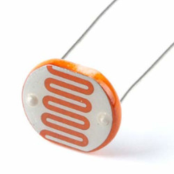
Here is a simple dark sensor circuit that is useful to switch ON and OFF any appliances automatically depending on the Light. As an output device, we’ll utilise a street lights/bulb in this example. If you are looking for LED as an output device, check this article. To detect the light, we will use an LDR (Light-dependent Resistor). As the name says, when the light intensity on LDR is high, the resistance through it decreases; when the light intensity on LDR is low, the resistance through it increases and becomes extremely high. It’s a kind of variable resistor, but the resistance varies based on the light.
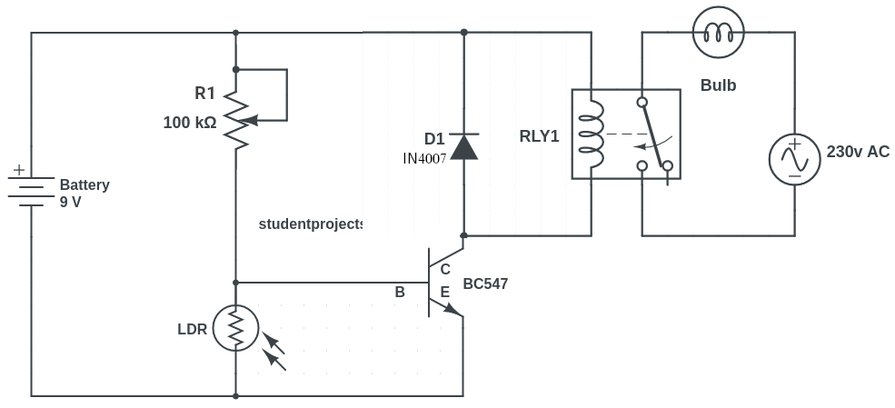
You must use a relay if you want to connect any heavy load. The Relay connection with the Dark Activated automated Light switch is shown in the circuit diagram below.
Circuit diagram
Components required
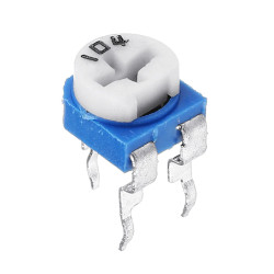
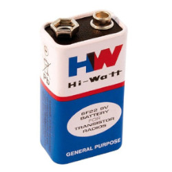
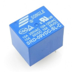
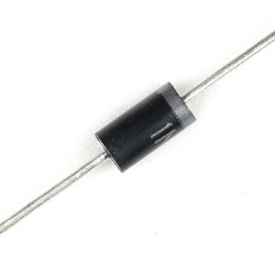
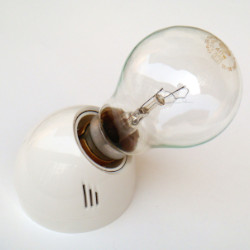
100k Ohm Potentiometer is a variable resistor that is used to change the trigger point for the LED. That is, how much light is needed for the LED to turn ON and OFF. You can also use a 50k Resister in the place of a variable resistor.
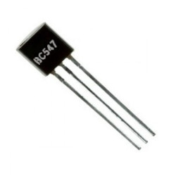
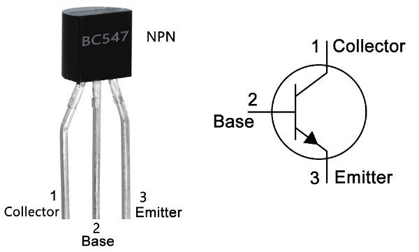
BC547 is an NPN transistor that is used to amplify the current. When there is a small current at its base, it controls the large current at its collector and emitter end.
1N4007 is a PN junction rectifier diode. This allows only the flow of electrical current in one direction only. So, it can be used for the conversion of AC power to DC.
A relay is an electrically operated switch.
How does it work?
During the daytime when there is a light, the LDR has very low resistance and all voltage coming through R1 dropped with the ground. This makes the voltage at the base of the transistor very low and it will not switch ON the transistor. Because the transistor is OFF, the current will not flow through the transistor. As a result, the relay will not be switched ON and the bulb remains OFF.
At night when there is no light, the LDR has high resistance and very less power dropped with the ground. This makes the voltage at the base of the transistor high to turn the transistor ON. Because the transistor is turned ON, current flows through the transistor. It flows from the positive battery terminal, through R2, the relay, and the transistor down to the negative battery terminal. As a result, the relay turns ON and hence the bulb turns ON.
The same circuit can be used for a variety of purposes.
So, give it a shot and let me know if you have any questions in the comments section below. I’ll be happy to assist you!
