AUTOMATIC SOLAR TRACKER starts following the SUN right from dawn, throughout the day, till evening, and starts all over again from dawn next day. On cloudy weathers, it remains still and catches the SUN again as it slips out of clouds. It does all this automatically, employs cheap and inexpensive components, and is very accurate.Let us see how it does all this.
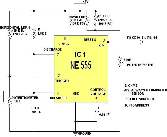
There are three Electronic Modules to be explained. First one is the HORIZONTAL SENSOR MODULE. It employs the timer 555 in the MONOSTABLE MODE. PIN 2(Trigger Pin of 555) is hooked up with a VOLTAGE DIVIDER NETWORK(PLEASE see FIGURE 2). PIN 4(Reset) is hooked up with ANOTHER VOLTAGE DIVIDER NETWORK.


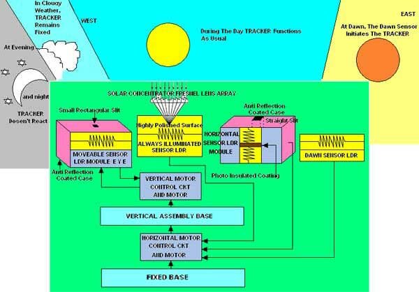
The LDR(SAY LDR A) which is always illuminated by light through FRESNEL LENS ARRAY, has Low Resistance(in presence of light resistance of LDR decreases and vice-versa). We know V(OUT)=V(IN)*[R(bottom)]/[R(bottom)+R(top)], where R stands For Resitance. So in SUNLIGHT, when LDR A’s resistance Decreases, VOLTAGE AT PIN 4 Increases. TIMER is no more RESET. PIN 2 is now lower than 1/3 rd Vcc(as the horizontal LDR 1, say LDR B does not initially receive light through its rectangular slit, so its resistance is high(Rtop=8 K ohms), consequently V(OUT) is low). This triggers the timer which gives a pulse to Decade Counter’s Clock(14) PIN and triggers it. The Decade Counter CD 4017 gives a NORMAL STEP DRIVE pulse to the Horizontal Unipolar Stepper Motor 1(coupled to the tracker unit) to rotate the tracker position so as to receive sunlight(STEP ANGLE of 2 DEGREES). This goes on till the horizontal LDR 1 is fully in SUNLIGHT(resistance low, so PIN 2’S VOLTAGE HIGH). Thus the tracker has followed the SUN Horizontally.

We will come to the Vertical Sensor Module, but first let us see what the DAWN LDR(SAY LDR C) does. At night the horizontal Module timer 555 remains Reset(as LDR A is in darkness so its resistance is high, thus pin 4 voltage is low, and the TRACKER points at WEST(where SUN has set). Next day when SUN rises again in the EAST, the DAWN LDR which is located at the back of the TRACKER, points at EAST. So when it receives sunlight its Resistance goes low, thus Voltage at pin 4 is high and the timer triggers the Decade Counter which in turn switches the Motor on, thus the TRACKER again moves towards the EAST. Then the TRACKER functions as previously.
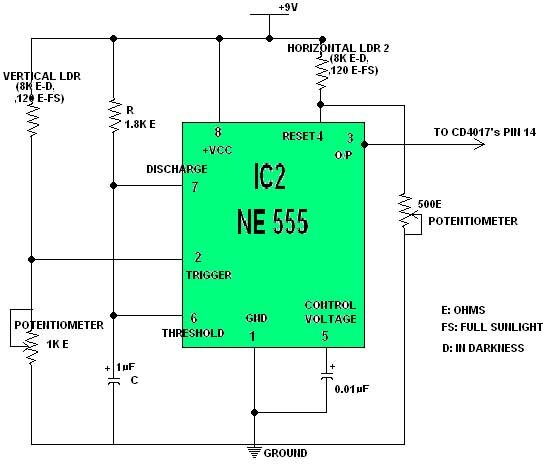
Now placed with the Horizontal Sensor LDR 1 is another similar LDR 2 which receives the sunlight as and when does LDR 1. SEE FIGURE 3. So now, as LDR B(THE 1st horizontal one) receives sunlight, so does Horizontal LDR 2(SEE FIGURE 1, THESE 2 LDRs are placed together with same alignment properties and separated by an optically insulated coating(from each other).Thus when Motor 1 comes to rest, and as the second horizontal LDR (SAY LDR D),is same way coupled to the second timer’s(of Vertical Module) Reset pin as was the ALWAYS ILLUMINATED LDR A, it brings the second timer out of its Reset mode) by the previously discussed VOLTAGE RELATIONSHIP). EYE SENSOR LDR(SAY LDR E) of the tracker receives sunlight by an Anti-Reflection Coated, small Rectangular Slit, so reacts only when SUN directly points at it. The second 555’s PIN 2 is same way connected to this LDR as was the first 555’s to Horizontal LDR 1. So now that it still not receives sunlight (resistance high, so Vout low) and pin 4 is no more Reset, the second CD 4017 MAKES THE SECOND STEPPER MOTOR 2 Rotate(Coupled so as to only rotate VERTICAL SENSING BLOCK/EYE BLOCK ). This movement continues till the SUN directly points at the EYE of our TRACKER. Then the TRACKER STOPS, pointing very accurately at the SUN.FIG 2 and FIG 3 follows.

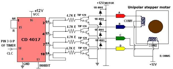
In figure 4 I have only shown the Horizontal Motor Control Circuit. The Vertical One uses a similar Decade Counter, NPN Transistors, Diodes(to encounter BACK EMF of Power Transistors due to Fast Switching). I chose for a Step Angle of 2 Degrees for the Unipolar Steppers. They are driven in a Normal 4 Step Sequence, first coil A is energised simultaneously with coil B ,then coil C with coil D. Thus the Motors rotate by 2 degrees each time. The Charging Interval(how long pin 3 of 555’s remains high) is almost in synchronism with the steps/second speed of the motors(here 600 steps/sec.), to avoid FALSE TRIGGERING.
NOTE:
- For 555 in MONOSTABLE MODE, T=1.1*R*C.
- For the FRESNEL LENS ARRAY , the standard FL 40(Focal Length=0.4 inches) Or FL 65(Focal Length=0.65 inches) FRESNEL LENSES could be used (with the Grooves facing the LDRs).
- For the ANTI-REFLECTION COATING, MULTI-LAYER COATING could be used to minimize loss due to REFLECTION. By using alternating layers of a Low-Index material like SILICA and a Higher-Index material, it is possible to obtain Reflectivities as low as 0.1% at Single Wavelength.
CONCLUSION:
We Conclude with the ADVANTAGES of the TRACKER MODULE SYSTEM:
- Uses SIMPLE, INEXPENSIVE ,EASY TO GET 555 timers and LDRs.
- The whole System draws only 25 MicroAmperes of Current when the Motors are not rotating.(555 timer’s off-state current req. is very less).BATTERY POWER IS SAVED.
- The TRACKER not only follows SUN from EAST to WEST and back to EAST in a cyclic manner(Horizontal Motor Module),but also tracks the Angular Movement of the SUN with respect to its ZENITH ANGLE to the Horizon(Vertical Motor Module and EYE).This is a VERSATILE quality for which the TRACKER could easily be used in conjunction with Solar Panels to derive maximum Solar Energy. Fast Motor Response(600 steps/sec.),no FALSE TRIGGERING, a Very ACCURATE System, it requires no Programming Devices(MICROPROCESSORS or MICROCONTROLLERS), so is NOT COMPLICATED.

plzzzzz sir give me full diteals&componant,program,conection etc
Is there any structural engineers or home builders online that would be interested in looking into the latest building system for homes and commercial? The system is for the entire shell of the building not just walls like others. It is Florida approved and is actually better in northern climates.
This circuit has never been tested. It does not work and will never work. All the outputs of the 4017 are connected TOGETHER!!!
It should be removed from the web. The author has been told about this but will not listen.
sir,
where it is manufactured? i want to purchase it.
Please send the cost details to my email before 20th of may, 2010. And details of how payment is to be made. thank you
Please send the cost details to my email before 20th of may, 2010. And details of how payment is to be made. thank you for immediate compliance.
I want atomatic microcontroller based horizontal and vertical
solar tracking project/ project kit any available.
Mail me the details and the cost of project
microcontroller version of this any details
i also want full description and component list abt auto sun tracking system
plz give me cost details within two days plz i need this urgent
sir,
I need the total informations,data including required pictures of
an automatic solar tracking system.give me full diteals&componant,
connection icluding pictures and required graphs.
kindly help me.pl send to my account immediately.
its urgent.
DO U HAVE ANY OTHER PROJECTS
plzzzzz sir give me full diteals&componant,program,conection etc, in sun tracker circuits
also the live support is perfect.
sir,
I need the total informations,data including required pictures of
an automatic solar tracking system.give me full diteals&componant,
connection icluding pictures and required graphs.
kindly help me.pl send to my account immediately.
its urgent.
I Want t0 information on solar tracking system.please give me guidence.
can you me the send me the full details and mechanical assembly of this project….
please………………
sorry for mistakes in last reply .sir I need your help why because I started to doing this project.
could you give me the details and mechanical assembly drawing and bill of components……
plz give me cost details within two days plz i need this urgent
plz give me the detail infomation about the ckt diagram ann poject……
sir, please give me all details of this project.it’s excellent project
now in these days it is necessary to save electricity.i like this
project.pls give me detail.
sir iam at std10 will you please suggest and sent me the pricelist of thsi project and were ican find one please sir its urgent i hope you’ll do it for me
I want atomatic microcontroller based horizontal and vertical
solar tracking project/ project kit any available.
Mail me the details and the cost of project
I want atomatic microcontroller based horizontal and vertical
solar tracking project kit any available.
Mail me the details and the cost of project,as soon as possible…
I am a student of b.tech(EC) final year
I’m interested in this project.
Can you please send me all the details and circuit diagram of this project with component list with its spacification.
I am a student of b.tech(EE) final year
I’m interested in this project.
Can you please send me all the details, cost and circuit diagram of this project with component list with its spacification.
I am a student of b.tech(EE) final year
I’m interested in this project.
Can you please send me all the details, cost and circuit diagram of this project with component list with its spacification.
What are it’s application??
I mean what are it’s uses, can you please tell me.
Thanks in advance.
Regards,
Jaya Krishna.
guess_jk4u@hotmail.com
………i want to do this project ..overall if we want to do it how much will it coast ….nd say its other applications?……pls sir i am in need of it…….thank u sir ..
To all those engineers who are asking for complete details, why the hell are you pursuing an Engineering degree? Please stop annoying the author. He has written a decent paper here and don’t bug him because of your stupidity. Period.
I am working as Technical officer in Agriculture University
I want to develop sensor panal on which 144 Light Dependant Resistance (LDR)
are connected. Whenever light is falls on any of the LDR it should be
shown on Computer screen and Time and date with LDR No. (which ldr was
on at which time and Date) should be store on computer in excel or any other convenient (table ) format. what will be the cost for it and is it possible?
can yoou help me in this regards
I am a student of b.e(EC) final year
I’m interested in this project.
Can you please send me all the details and circuit diagram of this project with component list with its spacification.
plzzzzzzz send the total informations,data including required pictures of
an automatic solar tracking system.give me full diteals&componant,
connection icluding pictures and required graphs.
kindly help me.pl send to my account immediately.
its urgent.
after Cd4017 all connectios getting shorted..
This circuit doesnt works
sir,i would like to implement this project.so may i get the further more details of this project.I hope you will provide me the more details.Thanking you,……
please give me cost details?
I Need all de infor of solar tracking system using stepper motor or dc motor sir………..?
& also need circuit diagram?
Hey guys my name is Ankil, I’m making a final year engineering project on Solar tracking systems, I guess many or all of you who’ve commented in this section are interested in the same. Lets share the knowledge and materials we’ve with us and help each other accomplish this project. Contact me at ankil19@hotmail.com or ankilsanghvi@live.com
sir i am the student of final year on bsc.i had send u msg already ,but i didnt get any reply from ur side….so can u plz give me quick reply
hi…,i am vaishali .can you please send me component details and circuit diagram.
hi my name is bruno could u give me a general idea of automatic solar tracker and inverter about 8 pages.so i will be in touch with this website.
thnk you
hello ! Ranjith ,
nice to know about your discribed solar tracker , especially the ‘conclusion’ .
i am not a so techno savvy , so , definitely i want to know the cost of this solar tracker . hope you dont mind selling one assembly piece .
please revert me on my email , swapnil(dot)shingvekar(at)gmail(dot)com.
thanks ! happy business !
wth warm regards,
Swapnil E.S.
layout of automatic solar tracker
hi ranjith. cud u think of any possible innovations dat can b implemented as a proj based on the above concept… say an application best suited fr solar tracking… somthing… il b glad to get a reply soon
thnkuuuuuuuuuuuuuuu.thnxx a lt
hi sir plz contact us
To you pretend EE CS or what ever majors. Is this how you got through school; copying someone else’s work? A real EE contender would realize that this circuit DOESN’T work. You have been told several times.
I built a circuit based on the LM339 comparator chip that has been working several years and has been published. much simpler and cheaper design.
Opinion: other than for hobby, this type of circuit is not practical for large or important applications. microprocessors are the way to go.
can you plz send me the proteus model and component details i am doing tracking project it will be nice to have your little assistance
Respect to internet site author , some good selective details .