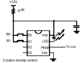
The RF section consists of an RF transmitter and an RF receiver. The RF transmitter mainly consists of a remote key that contains a code hopping encoder, HCS301 along with 2 buttons and two LEDs. The RF receiver section consists of a Low Power ASK receiver IC. The key encoder will generate the company specific “Company ID”, which will be decoded by the low power ASK receiver IC. The LEDS are used to show the status of the remote key. The two buttons provided are used for ‘entry’ and ‘exit’. When both the buttons are pressed together, the system goes into a ‘panic’ state wherein the system will turn on the siren and immobilize the vehicle in emergency condition after a 10sec delay.
THE TRANSMITTER UNIT:
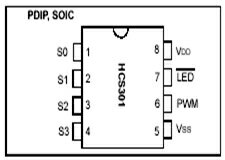
The transmitter consists of a code hopping encoder, HCS301 from Microchip Technology. The HCS301 utilizes the KEELOQ code hopping technology, which incorporates high security, a small package security, a small package outline and low cost, to make this device a perfect solution for unidirectional remote keyless entry systems and access control systems.
The HCS301 combines a 32-bit hopping code, generated by a nonlinear encryption algorithm, with a 28-bit serial number and 6 information bits to create a 66-bit code word. The code word length eliminates the threat of code scanning and the code hopping mechanism makes each transmission unique, thus rendering code capture and resend schemes useless. The crypt key, serial number and configuration data are stored in an EEPROM array, which is not accessible via any external connection. The EEPROM data is programmable but read-protected. The data can be verified only after an automatic erase and programming operation. This protects against attempts to gain access to keys or manipulate synchronization values. The HCS301 provides an easy-to-use serial interface for programming the necessary keys, system parameters and configuration data.
Security
- Programmable 28-bit serial number
- Programmable 64-bit encryption key
- Each transmission is unique
- 66-bit transmission code length
- 32-bit hopping code
- 34-bit fixed code (28-bit serial number,
- 4-bit button code, 2-bit status)
- Encryption keys are read protected
Operating
- 3.5V – 13.0V operation
- Four button inputs
- No additional circuitry required
- 15 functions available
- Selectable baud rate
- Automatic code word completion
- Battery low signal transmitted to receiver
- Battery low indication on LED
- Non-volatile synchronization data
Other
- Functionally identical to HCS300
- Easy-to-use programming interface
- On-chip EEPROM
- On-chip oscillator and timing components
- Button inputs have internal pull-down resistors
- Current limiting on LED output
- Low external component cost


The HCS301 is a simple device to use. It requires only the addition of buttons and RF circuitry for use as the transmitter in your security application. The HCS301 will wake-up upon detecting a button press and delay approximately 10 ms for button debounce. The synchronization counter, discrimination value and button information will be encrypted to form the hopping code. The hopping code portion will change every transmission, even if the same button is pushed again. A code word that has been transmitted will not repeat for more than 64K transmissions. This provides more than 18 years of use before a code is repeated; based on 10 operations per day. Overflow information sent from the encoder can be used to extend the number of unique transmissions to more than 192K. If in the transmit process it is detected that a new button(s) has been pressed, a RESET will immediately occur and the current code word will not be completed. Please note that buttons removed will not have any effect on the code word unless no buttons remain pressed; in which case the code word will be completed and the power-down will occur.
Code Word Format:
The HCS301 code word is made up of several parts. Each code word contains a 50% duty cycle preamble, a header, 32 bits of encrypted data and 34 bits of fixed data followed by a guard period before another code word can begin.

 Code Word Organization:
The HCS301 transmits a 66-bit code word when a button is pressed. The 66-bit word is constructed from a Fixed Code portion and an Encrypted Code portion. The 32 bits of Encrypted Data are generated from 4 button bits, 12 discrimination bits and the 16-bit sync value. The encrypted portion alone provides up to four billion changing code combinations. The 34 bits of Fixed Code Data are made up of 2 status bits, 4 button bits and the 28-bit serial number. The fixed and encrypted sections combined increase the number of code combinations to 7.38 x 10¹⁹.
Code Word Completion:
The code word completion feature ensures that entire code words are transmitted, even if the button is released before the code word is complete. If the button is held down beyond the time for one code word, multiple code words will result. If another button is activated during a transmission, the active transmission will be aborted and a new transmission will begin using the new button information.
THE RECEIVER UNIT:
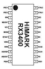
The receiver unit consists of the RX3400, which is a low power ASK receiver IC, and is suitable for use in a variety of low power radio applications including remote keyless entry. The RX3400 is based on a single-conversion, super-heterodyne receiver architecture and incorporates an entire phase-locked loop (PLL) for precise local oscillator generation.
Features

- Extremely low power operation
- Low external part count
- Receiver input frequency: 290 – 460 MHz
- On-chip VCO with integrated PLL using crystal oscillator reference
- PLL power down feature
- Integrated IF and data filters
- SSOP-24 package (0.64 mm pitch)
Functional Description
The RX3400 ASK receiver IC incorporates an LNA; mixer; PLL-based local oscillator including VCO, fixed divider (÷ 64), reference crystal oscillator, phase-frequency detector (PFD), and charge pump; IF filter; logarithmic amplifier; data filter; peak detector; and 1- bit comparator and is capable of demodulating ASK input signals.
PLL Power-down Function
The PLL portion of the IC can be powered up and down through the control of the PD input (pin 14). During PLL power down operation (pin 14 pull low), the reference crystal oscillator, fixed VCO divider, PFD, and charge pump are all shut off and the current consumption of the IC drops by approximately 600mA. The VCO circuitry remains on and may be configured to operate as a buffer amplifier for an external SAW-based oscillator.
1-bit Comparator
The integrated 1-bit comparator operates as a data slicer and “squares up” the data filtered RSSI output from the logarithmic amplifier. The decision threshold voltage level for the 1-bit comparator is stored on an external capacitor connected to the ASKREF pin.

Thanks for the information! I personally really appreciate your article. This is a great website. I will make sure that I stop back again!.