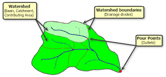
Goal and Principle the major goal of this analysis is to determine the maximum amount of water that can reasonably be anticipated to enter the drainage system under consideration. Runoff is the term for the remaining rainwater after some has evaporated and been absorbed sloshes across the top. The pace of rainfall, type of soil, topography, and other variables all has an impact on runoff plant life, etc. All surface water should be drained away via the surface drainage that will be designed. In this analysis, first, the specifics of the areas average intensity for a chosen frequency and duration. It is necessary to set aside time for concentration. Then, depending on the total and peak rainfall Determined for the area under consideration is a pre-set intensity.

HYDRAULIC DESIGN:
Once the maximum discharge has been determined, the side drains and culverts are now constructed using the principles of flow through open channels.
Then, Q = AV
Where,
Q is the quantity of the surface water in m3 /s to be removed from side drains.
V is the velocity of the water in the channel.
A is the required area of the drain.
Using Manning’s equation and the assumptions of uniform and constant flow across a uniform cross section and slope, the velocity is computed.
V=1/n R2/3S1/2
The types of soil in unlined channels affect the roughness coefficient (n) values. Roughness coefficient n is equal to 0.02 for normal earth, but 0.005 to 0.1 for earth covered in dense grass or plants. The kind of lining affects the roughness coefficient in channels with linings. The value of n is 0.013 for well-finished concrete and 0.04 for coarse debris and riprap.
Design Steps:
- Using Manning’s equation, the hydraulic radius is determined for a permitted non-scouring velocity.
- The maximum discharge and the permitted non-scouring velocity are used to calculate the minimum cross-sectional area.
- Determine the dimensions of the drain, i.e., the breadth and width, by linking the area and perimeter. Calculate the wetted perimeter.
- If the depth is less than the critical depth, erosion may occur at the downstream end, necessitating a revision of the process or the provision of specific measures at the downstream. The depth of flow found should be more than the critical depth [v2 /g].
