The design aspects of sedimentary tanks are
- Velocity of flow
- Capacity of tank
- Inlet and outlet arrangements
- Shapes of tanks
1. Flow velocity:
The flow velocity of water in sedimentation tanks should be high enough to cause suspended pollutants to sink hydraulically. It should be consistent throughout the tank and not exceed 150mm to 300mm per minute in most cases.
2. Tank capacity:
Tank capacity is computed using the following formula:
2.1 Detention period: The detention period is the theoretical time it takes for a particle of water to travel between the entry and exit of a settling tank. The tank’s capacity is determined by
| C = Q x T where | C | Capacity of tank |
| Q | Discharge or rate of flow | |
| T | Detention period in hours |
The length of detention is determined by the quality of suspended contaminants in the water. The detention period for plain sedimentation tanks has been reported to range from 4 to 8 hours.
2.2 Overflow Rate: in this method, it is assumed that the settlement of a particle at the bottom of the tank is independent of the tank’s depth and is determined by the tank’s surface area.
Where
L -> Length of tank
B -> Breadth of tank
D -> Depth of tank = Side water depth = S.W.D
C -> Capacity of tank
T -> Detention period
U -> Discharge or rate of flow
V -> Velocity of descent of a particle to the bottom of the tank = Surface overflow rate = S.O.R.
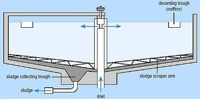
3. Inlet And Outlet Arrangements
The inlet is a device that is used to distribute water within a tank, and the outlet is a device that collects the water that is discharged. These arrangements should be correctly built and placed so that they do not hinder or disrupt the flow of water.
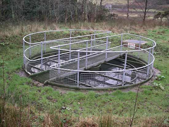
4. Shapes of tanks
Following are the three shapes of the settling tank.
- Rectangular tanks with horizontal flow
- Circular tanks with radial or spiral flow
- Hopper bottom tanks with vertical flow
The following are the parameters for satisfactory performance.
| 1 | Detention period | 3 to 4 hours for plain settling 2 to 21/2 hours for coagulant settling 1 to 11/2 hours for up-flow type |
| 2 | Overflow rate | 30 – 40 m3/m2/day for horizontal flow 40-50m3/m2/day for up flow |
| 3 | Velocity of flow | 0.5 to 1.0 cm/sec |
| 4 | Weir loading | 300m3/m/day |
| 5 | L: B | 1:3 to 1:4 |
| 6 | Breadth of tank | (10 to 12m) to 30 to 50m |
| 7 | Depth of tank | 21/2 – 4m |
| 8 | Dia of the circular tank | up to 60m |
| 9 | Solids removal efficiency | 50% |
| 10 | Turbidity of water after sedimentation | 15 to 20 N.T.U. |
| 11 | Inlet and Outlet zones | 0.75 to 1.0m |
| 12 | Freeboard | 0.5m |
| 13 | Sludge Zone | 0.5m |
Sedimentation Aided With Coagulation
Fine clay and electrically charged colloidal particles in water are always in motion and never settle down due to gravity force. Chemicals are added to the water to remove pollutants that would not be removed by sedimentation alone. During its development and descent through water, the chemical form of insoluble, gelatinous, flocculent precipitate absorbs and engulfs very fine suspended particles and colloidal contaminants. Additionally, these coagulants have the benefit of eliminating colour, odour, and taste from the water. Water turbidity was reduced by up to 5-10 ppm, and bacteria were removed by up to 65 percent.
The following are the most used Coagulants with normal dose and PH values required for best floc formation as shown in Table.
| Sl.No. | Coagulant | PH Range | Dosage mg/l |
| 1. | Aluminium sulphate Al2(SO4)3, 18 H2O | 5.5 – 8.0 | 5 – 85 |
| 2. | Sodium Aluminate, Na2Al2O4 | 5.5 – 8.0 | 3.4 – 34 |
| 3. | Ferric Chloride (Fecl3) | 5.5 – 11.0 | 8.5 – 51 |
| 4. | Ferric Sulphate Fe2 (SO4)3 | 5.5 – 11.0 | 8.5 – 51 |
| 5. | Ferric Sulphate FeSO47H2O | 5.5 – 11.0 | 8.5 – 51 |
Coagulants are selected based on the PH of the water. Because of its inexpensive cost and simplicity of storage as solid crystals over long periods of time, alum or aluminium sulphate is commonly utilised in all treatment plants.
The amount of coagulant that should be added to the water is determined by the type of coagulant, the turbidity of the water, the colour of the water, the PH of the water, and the temperature of the water, and the mixing and flocculation time. A Jar test is used to evaluate the appropriate coagulant dose for a water treatment plant, as depicted.
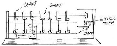
To begin the experiment, a sample of water is taken in each jar, and the coagulant is applied in variable amounts to each jar. In each jar, the amount of coagulant added is recorded. The paddles are then rotated at a speed of 30-40 R.P.M. for around 10 minutes using an electric motor. The pace is then slowed, and the paddles are spun for 20-30 minutes. The paddles’ revolution is halted, and the floc that forms in each Jar is documented and allowed to settle. The optimum coagulant dose is the dose of coagulant that produces the best floc.
The coagulants may be fed or allowed to enter either in powder form called dry feeding or in solution form called wet feeding. The mixing of coagulant with the water to form the floc by the following methods.
- Centrifugal pump
- Compressed air
- Hydraulic jump
- Mixing channel
- Mixing basins with baffle walls
- Mixing basins with mechanical means