Imagine the convenience, if we could control different devices at home/industry by using a single PC. Our project aims at the same and could be used to control the printer power, loads & other household electrical appliances. The circuit comprises decoder, inverter, latch & relay driver sections. To control these equipments we are using PC’s Parallel port. The program of controlling is written in C language. It is compiled using Turbo C compiler.
The project though a bit expensive, is very efficient in control of real world peripherals.
Contents:
- INTRODUCTION
- PARTS LIST
- BLOCK DIAGRAM
- COMPONENT DESCRIPTION
- Parallel Port
- IC 74LS154
- IC 74LS74
- 1C 74 LS05
- 1C ULN 2803
- Relay
- CIRCUIT DESCRIPTION AND WORKING
- SOFTWARE PROGRAM
- CONCLUSION
INTRODUCTION:
The PC parallel port is an expensive yet a powerful platform for implementing projects dealing with the control of real-world peripherals. This port can be used to control the printer as also household and other electrical appliances. The computer program through the interface circuit controls the relays, which, in turn, switch the appliances on or off.
The parallel port has 12 outputs including 8 data lines and 4 control lines. The circuit described here can be used to control up to 255 electrical appliances using only eight data lines from the parallel port. Besides, the software program allows the users to know the current status of the loads.
PARTS LIST:
Semiconductors:
ICl, IC2, IC3 – 74LS154 l-of-16 decoder
IC4, IC5, IC6 – 74LSO5 inverter
IC7-ICI4 – 74LS74 D-type flip/flop
ICI5, IC16 – ULN2803 octal Darlington array driver
Misc.
Power supply – 5V regulated DC, 12VregulatedDC
Relay – 12V,200-ohm, lC/O SPDT
BLOCK DIAGRAM:
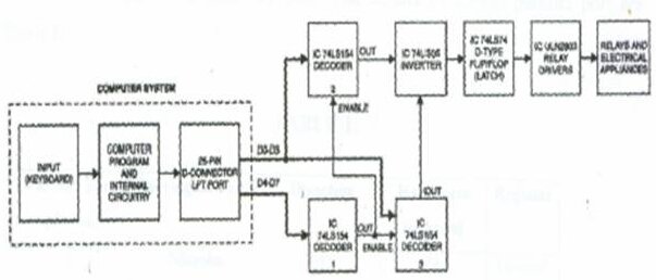
The block diagram in Fig. 1 depicts the main components of the switching system for 255 electrical loads using PC. The control command to switch on/off the appliances is given through the keyboard. The software program scans the input and as per the input command, the data is available at the parallel port.

Out of eight bits, first four bits (D0 through D3) are data signal bits and the remaining four bits (D4 through D7) are used as control signals. Control signals are given to decoder 1. The output of decoder 1 is given to Enable pins of decoders 2 and 3. Data signals are given to both decoders 2 and 3. The outputs of decoders 2 and 3 are inverted and fed to a D-type flip/flop that is used to latch the data. The latched data output is given to relay driver ICs ULN2803. The relay drivers drive the relays for switching the appliances.
COMPONENT DESCRIPTION:
1. THE PARALLEL PORT:
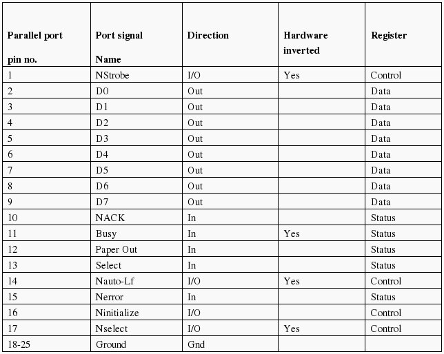
The parallel port or line printer terminal (LPT) port is a 25-pin D-type female connector available at the back of your PC. A basic IBM PC usually comes with one or two LPT ports. The original parallel port, called standard parallel port (SPP), is a bundle of three ports (or registers), namely, data port, status port, and control port. Pins 2 through 9 form the 8-bit data port. This port is purely a write-only port. This means it can be used only to output some data through it. Pins I, 14, 16, and 17 form the control port, which is capable of reading/writing. Pins 10 through 13 and pin 15 together form the status port. The status port is a read-only port. The details of 25-pin parallel port are given in Table 1.

The base address of the first parallel port (LPT1) is 0378 in hexadecimal (hex) notation (or 888 in decimal notation). The base address of the second parallel port (LPT2) is 0278 in hex. In this project, we’ve used only LPT1.
2. DM74LS154 : 4-LINE TO 16-LINE DECODER / DE-MULTIPLEXER:
Each of these 4-line-to-16-line decoders utilizes TTL circuitry to decode four binary-coded inputs into one of six-teen mutually exclusive outputs when both the strobe inputs, GI and G2, are LOW. The de-multiplexing function is performed by using the 4 input lines to address the out-put line, passing data from one of the strobe inputs with the other strobe input LOW. When either strobe input is HIGH, all outputs are HIGH. These de-multiplexers are ideally suited for implementing high-performance memory decoders.
All inputs are buffered and input clamping diodes are provided to minimize transmission line effects and thereby simplify system design.
3. 74LS74 : DUAL D-TYPE POSITIVE-EDGE-TRIGGERED FLIP-FLOPS:
These devices contain two independent D-type positive-edge triggered flip-flops. A low level at the preset or clear inputs sets or resets the outputs regardless of the levels of the other inputs. When preset and clear are inactive (high), data at the D input meeting the setup time requirements are transferred to the outputs on the positive-going edge of the clock pulse. Clock triggering occurs at a voltage level and is not directly related to the rise time of the clock pulse. Following the hold time interval, data at the D input may be changed without affecting the levels at the outputs.
4. HEX INVERTER:
It is used for inversion of input signal. Since outputs from the de-multiplexers are active low, we invert them. This IC has 6 not-gates and hence called a hex-inverter.
5. ULN-2803 : OCTAL PERIPHERAL DRIVER ARRAYS:
The eight NPN Darlington connected transistors in this family of arrays are ideally suited for interfacing between low logic level digital circuitry (such as TTL, CMOS or PMOS/NMOS) and the higher current/voltage requirements of lamps, relays, printer hammers or other similar loads for a broad range of computer, industrial, and consumer applications. All devices feature open-collector outputs and freewheeling clamp diodes for transient suppression. The ULN2803 is designed to be compatible with standard TTL families while the ULN2804 is optimized for 6 to 15volt high-level CMOS or PMOS.
6. RELAYS:
The relay is a device by means of which an electrical circuit can be controlled (opened or closed) by sensing a change in the circuit in which it is connected. The relays can be either electromagnetic or electronic. In this circuit the electromagnetic relay is used to connect or disconnect the supply to the appliance to be controlled. It works on the principle of electromagnetic attraction and electromagnetic induction. These relays can be actuated by AC or DC quantities. In these relays there are one or more coils, movable elements, contact systems etc.

i want to know the method of switching using microcontrollers
PLEASE SAND ME SOURCE CODE OF CONTROLING POWER BY PC IN JAVA LANGUAGE……….
it can control device, can it be used to montior voltage and some I/O signal and the same time?
is there RS232 VERSION instead of parallel port?
thank you
i want to download the schematic diagram of device switching using pc’s parallel port
hi.. i want to download the source code of device switching using pc’s parallel port in c#.net sp please forward it to my email-id its urgent require so please please send code to me
I have tried the program but it does not give the desired outpt though it prints what you have showed in your screen shots..Kindly help us as it is related to the filnal year project..Please !!!!
We have taken this project & got selected but now there is a problem…………
I have tried to make the artwork & layout but it does not succeded.
Kindly help us as it is related to the third year project as soos as possible..Please send the same on my e-mail id OR give us direction!!!!
Please help us >>>>>> to download the schematic diagram of device switching using pc’s parallel port.
we have to submit our project upto end of this month… PLEASE HURRY & HELP US….
I would like to build the circuit and test it. Can you please send me the source code. I also do not have a turbo compiler.
Regards,
Iqbal
i want to do the project which is control of electrical appliance such asaaaaaa
a bulb but i have problem with the programmation how can i sort it?
i find it difficult to locate pin no. of ic74ls93,74ls75 , 74f139, can you help/
though i liked the project & wanted to go through the entire project but i could not see the last part of the project..every time i clicked on the page links..only the 1st page is getting re-opened..plzz help…i need it…if possible plzzz send me a copy of the entire project in my email-id
i have this project circuit diagram,coding,pcb,all components and a
hard copy of this project.contact jai.mishra@ymail.com
Please send me the full project report and Code of project.
when i run the code, it has a lot of error
i run it in visual studio
because i have widow 7 and i don’t know how to download it
Its superb as your other articles : D, thankyou for putting up. “What makes something special is not just what you have to gain, but what you feel there is to lose.” by Andre Agassi. star wars dvd box http://www.netaddiction.com/index.php?option=com_blog&view=comments&pid=188659&Itemid=0
I love your blog.. very nice colors & theme. Did you design this website yourself or did you hire
someone to do it for you? Plz answer back as I’m looking to design my own blog and would like to find out where u got this from. kudos
I think that is one of the such a lot significant info for me.
And i am satisfied reading your article.
However should remark on few basic things, The web site taste is great, the articles is in reality nice
: D. Excellent process, cheers
Ahaa, its fastidious conversation concerning this
post at this place at this website, I have read all that, so at this
time me also commenting here.
Every weekend i used to visit this site, for the
reason that i wish for enjoyment, as this this website conations in fact good funny information too.
Failed to get the source code for device switching using parallel port working.