This project is actually an educational kit. One can study the full operation of unipolar type stepper motor using this board. As it is micro controller based it can be programmable also and one can learn micro controller interfacing with LEDs, key board and stepper motor. Thus single board serves the purpose of learning stepper motor control as well as learning micro controller programming.
General description and system block diagram:-
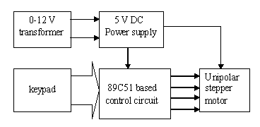
The complete board consists of transformer, control circuit, keypad and stepper motor as shown in snap. The given figure shows the block diagram of project.

The circuit has inbuilt 5 V power supply so when it is connected with transformer it will give the supply to circuit and motor both. The 8 Key keypad is connected with circuit through which user can give the command to control stepper motor. The control circuit includes micro controller 89C51, indicating LEDs, and current driver chip ULN2003A. One can program the controller to control the operation of stepper motor. He can give different commands through keypad like, run clockwise, run anticlockwise, increase/decrease RPM, increase/decrease revolutions, stop motor, change the mode, etc. before we start with project it is must that we first understood the operation of unipolar stepper motor.
Unipolar stepper motor:-
In the construction of unipolar stepper motor there are four coils. One end of each coil is tide together and it gives common terminal which is always connected with positive terminal of supply. The other ends of each coil are given for interface. Specific color code may also be given. Like in my motor orange is first coil (L1), brown is second (L2), yellow is third (L3), black is fourth (L4) and red for common terminal.
By means of controlling a stepper motor operation we can
- Increase or decrease the RPM (speed) of it
- Increase or decrease number of revolutions of it
- Change its direction means rotate it clockwise or anticlockwise
To vary the RPM of motor we have to vary the PRF (Pulse Repetition Frequency). Number of applied pulses will vary number of rotations and last to change direction we have to change pulse sequence.
So all these three things just depends on applied pulses. Now there are three different modes to rotate this motor
- Single coil excitation
- Double coil excitation
- Half step excitation
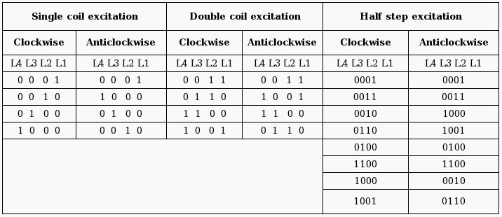
The table given below will give you the complete idea that how to give pulses in each mode

Note:- In half step excitation mode motor will rotate at half the specified given step resolution. Means if step resolution is 1.8 degree then in this mode it will be 0.9 degree. Step resolution means on receiving on 1 pulse motor will rotate that much degree. If step resolution is 1.8 degree then it will take 200 pulses for motor to compete 1 revolution (360 degree).
Now let me give you the specification of the stepper motor that I have used.
Max rated voltage: – 5 V
Max rated current per coil: – 0.5 Amp
Step resolution: – 1.8 degree / pulse
Max RPM: – 20 in single/double coil excitation mode and 60 in half step mode
Torque: – 1.5 Kg/cm2
RPM calculation:-
One can calculate the exact RPM at which motor will run. We know that motor needs 200 pulses to complete 1 revolution. Means if 200 pulses applied in 1 second motor will complete 1 revolution in 1 second. Now 1 rev. in 1 sec means 60 rev. in 1 minute. That will give us 60 RPM. Now 200 pulses in 1 sec means the PRF is 200 Hz. And delay will be 5 millisecond (ms). Now lets see it reverse.
* If delay is 10 ms then PRF will be 100 Hz.
* So 100 pulses will be given in 1 sec
* Motor will complete 1 revolution in 2 second
* So the RPM will be 30.
In same manner as you change delay the PRF will be changed and it will change RPM
Stepper motor control board circuit:-

The circuit consists of very few components. The major components are 7805, 89C51 and ULN2003A.
Connections:-
- The transformer terminals are given to bridge rectifier to generate rectified DC.
- It is filtered and given to regulator IC 7805 to generate 5 V pure DC. LED indicates supply is ON.
- All the push button micro switches J1 to J8 are connected with port P1 as shown to form serial keyboard.
- 12 MHz crystal is connected to oscillator terminals of 89C51 with two biasing capacitors.
- All the LEDs are connected to port P0 as shown
- Port P2 drives stepper motor through current driver chip ULN2003A.
- The common terminal of motor is connected to Vcc and rest all four terminals are connected to port P2 pins in sequence through ULN chip.
Now by downloading different programs in to 89C51 we can control the operation of stepper motor. Let us see all different kind of program.

da program gives syntax error when it is build in keil software.
its give error for cjne a,#0ffh,jmp. n
jmp clr p0.0……..
Hi, here jmp is used as a label. Please change jmp to some other name. for example
cjne a,#0ffh,keypress
keypress: clr p0.0
it also gives error here
lop2:mov r6,#FAh ; give 1 ms delay :the error is undefined symbol(pass 2).
lop2: mov r6,#0FAh ; for 200ms delay : attempt to define already defined label.
lop1: nop attempt to define already defined label.
hi plz tell me abt these error in program
n i m using of Seiko epson EM-198.
will it operate with 7805.
Hi replace “dely” function as given below.
———————-
dely:
mov r5,#0C8h ; load count 200
lop22: mov r6,#0FAh ; for 200ms delay
lop11:nop
nop
djnz r6,lop11
djnz r5,lop22
ret
———————–
Nothing seems to be easier than seeing someone whom you can help but not helping.
I suggest we start giving it a try. Give love to the ones that need it.
God will appreciate it.
I’m new here on the forum, found it by searching google. I look forward to chatting about various topics with all of you.
It is interesting. Can you mail me the full details of the circuits
Good stuff. I like this blog. I will subscribe to it.
very good circuit … can you mail the full details and explainations of the circuit.
can u tell me how to control pitman motor using at89s51 through h bridge give ,jut move the motor in forward and reverse direction ,and also give me a small cobe to drive the motor through h bridge using at89s51
sperb thank u
А телефон свой не оставите? Хотелось бы кое-что обсудить по теме.
hey the project is nice but is there any problem in the programs is they give error
hi, please give the full information about the stepper motor
Nice project for learners. Is it available in kit form at a reasonable price?
Are the problems solved or still existing?
Cheers, superb post.
Hi . . .can you mail me the full detail of the circuit diagram and the
program.
AS THIS IS IN ASSEMBLY AND NOT IN ‘C’ DONT USE KEIL USE “ASEM” OR “RAISONANCE” INSTEAD.
in new ustzz
Hi there, just wandered by. I have a Cincinnati 4g site. Amazing the amount of information on the web. Wasn’t what I was looking for, but great site. Take care.
hello sir,
I am a final year student of electronics and communication engineering and project implementation. please i need the complete circuit diagram. and I sincerely request you to send the full schematic of the “high-rise car park automation systems” my email id nguyenlinh1092@gmail.com
plz snd me keil code anyone
thankx alot
plz snd me any one keil code
thankx guys
Hi to every one, since I am truly keen of reading this blog post to be updated daily. It contains pleasant information.
hello sir pls send the keil c program for this control circuit
thank u