Examples:

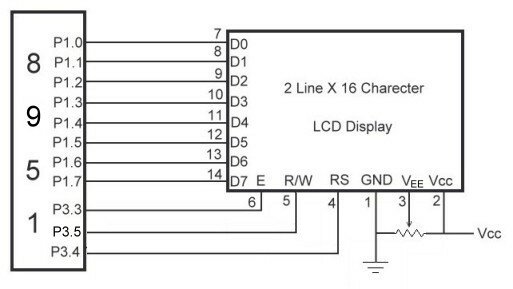
Here Data pins D0-D7 are connected to port1.0-port1.7 of 8951 microcontroller. Enable pin, RS are connected to P3.3 and P3.4 of 8951 respectively.
We can write program for LCD in two ways.
- Sending commands and data to LVDs with a time delay.
- Sending commands and data to LVDs with checking busy flag.
1. Program to display “ELECTROFRIENDS” in LCD without checking busy flag.
MOV A,#38H ; initialization LCD 2lines, 5×7 matrix.
ACALL COMMAND ; call command subroutine.
ACALL DELAY ; call delay subroutine.
MOV A,#0EH ; display on, cursor on
ACALL COMMAND
ACALL DELAY
MOV A,#01H ; Clear LCD
ACALL COMMAND
ACALL DELAY
MOV A,#06H ; shift cursor right
ACALL COMMAND
ACALL DELAY
MOV A,#80H ; cursor at beginning of 1st line
ACALL COMMAND
ACALL DELAY
MOV A,#’E’ ; display letter E
ACALL DATA
ACALL DELAY
MOV A,#’L’ ; display letter L
ACALL DATA
ACALL DELAY
MOV A,#’E’ ; display letter E
ACALL DATA
ACALL DELAY
MOV A,#’C’ ; display letter C
ACALL DATA
ACALL DELAY
MOV A,#’T’ ; display letter T
ACALL DATA
ACALL DELAY
MOV A,#’R’ ; display letter R
ACALL DATA
ACALL DELAY
MOV A,#’O’ ; display letter O
ACALL DATA
ACALL DELAY
MOV A,#’F’ ; display letter F
ACALL DATA
ACALL DELAY
MOV A,#’R’ ; display letter R
ACALL DATA
ACALL DELAY
MOV A,#’I’ ; display letter I
ACALL DATA
ACALL DELAY
MOV A,#’E’ ; display letter E
ACALL DATA
ACALL DELAY
MOV A,#’N’ ; display letter N
ACALL DATA
ACALL DELAY
MOV A,#’D’ ; display letter D
ACALL DATA
ACALL DELAY
MOV A,#’S’ ; display letter S
ACALL DATA
ACALL DELAY
HERE: JMP HERE
COMMAND: MOV P1,A ; Send command to LCD
CLR P3.4 ; RS=0 for command
CLR P3.5 ; R/W=0 for write
SETB P3.3 ; E=1 for high pulse
CLR P3.3 ; E=0 for H-to-L pulse
RET
DATA: MOV P1,A ; Write data to LCD
SETB P3.4 ; RS=1 for data
CLR P3.5 ; R/W=0 for write
SETB P3.3 ; E=1 for high pulse
CLR P3.3 ; E=0 for H-to-L pulse
RET
DELAY: MOV R2,#50
D1: MOV R3,#0FFH
D2: DJNZ R3,D2
DJNZ R2,D1
RET
2. Program to display “ELECTROFRIENDS” in LCD with checking busy flag.
MOV A,#38H ; initialization LCD 2lines, 5×7 matrix.
ACALL COMMAND ; call command subroutine.
MOV A,#0EH ; display on, cursor on
ACALL COMMAND
MOV A,#01H ; Clear LCD
ACALL COMMAND
MOV A,#06H ; shift cursor right
ACALL COMMAND
MOV A,#80H ; cursor at beginning of 1st line
ACALL COMMAND
MOV A,#’E’ ; display letter E
ACALL DATA
MOV A,#’L’ ; display letter L
ACALL DATA
MOV A,#’E’ ; display letter E
ACALL DATA
MOV A,#’C’ ; display letter C
ACALL DATA
MOV A,#’T’ ; display letter T
ACALL DATA
MOV A,#’R’ ; display letter R
ACALL DATA
MOV A,#’O’ ; display letter O
ACALL DATA
MOV A,#’F’ ; display letter F
ACALL DATA
MOV A,#’R’ ; display letter R
ACALL DATA
MOV A,#’I’ ; display letter I
ACALL DATA
MOV A,#’E’ ; display letter E
ACALL DATA
MOV A,#’N’ ; display letter N
ACALL DATA
MOV A,#’D’ ; display letter D
ACALL DATA
MOV A,#’S’ ; display letter S
ACALL DATA
HERE: JMP HERE
COMMAND: CALL READY ; check whether LCD is ready
MOV P1,A ; Send command to LCD
CLR P3.4 ; RS=0 for command
CLR P3.5 ; R/W=0 for write
SETB P3.3 ; E=1 for high pulse
CLR P3.3 ; E=0 for H-to-L pulse
RET
DATA: CALL READY ; check whether LCD is ready
MOV P1,A ; Write data to LCD
SETB P3.4 ; RS=1 for data
CLR P3.5 ; R/W=0 for write
SETB P3.3 ; E=1 for high pulse
CLR P3.3 ; E=0 for H-to-L pulse
RET
READY: SETB P1.7 ; make P1.7 input port
CLR P3.4 ; RS=0
SETB P3.5 ; R/W=0 for read
UP: SETB P3.3 ; E=1 for high pulse
CLR P3.3 ; E=0 for H-to-L pulse
JB P1.7, UP ; stay until LCD is busy
RET

Can i get more detail about it
good one…. nice!!!!!!!!1
This is a tutorial on alphanumeric 16×2 lcd interfacing with AT89C51.The programming algorithm is compatible with HITACHI HD44780U lcd controller .Complete programming code is given with neat circuit diagram.
Hi there, I just found this website whilst searching around the Internet as I am looking for some info on LCD TVs!. It’s an informative blog so I have bookmarked your site and I intend to return tomorrow to enjoy a proper read when I have more time.
please send me more details about microcontroller 8951
thx alot im elahe ,student of electronic engineering i use it for my project of 8051
Dear sir,
Thanks for posting the project.
i am running through the last semester. Would you please provide us the complete circuit diagram of this project?
the complete circuit diagram of this project would be really helpful, thank u
i want the interfacing circuit of lcd and adc 0804 for 89c51 microprocessor
how to produce backlight in 2×16 lcd display