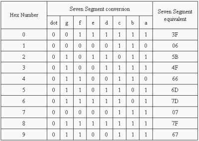
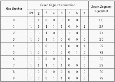
Calculation of lookup table as follows:
The lookup table contains the input pattern for the LED legs, to display the corresponding digits.
The table shows the seven segment requirement pattern to display the Hex number, with the Seven segment conversion.
For example, Let us consider the display of the number 0, where we need to switch ON all the LEDs which are there at the boundary. i.e. for a CC LED, we should supply 5 volts to these LEDs. The 6 LEDs (‘a’ through ‘f’) should get binary 1, the dot and the (middle) hyphen segment should get 0Volts or the binary Zero. Effectively the Seven segment pattern code will be (0011 1111) 3Fh. That is what we OUT through the port pins.
For a Common Anode LED, the display pattern will be the complement of that of Common Cathode pattern.
For Common Cathode :

For common Anode:

ASM program:
This program displays characters 0 through 9 on seven-segment display connected directly to the port 2 of the microcontroller Intel8951.
Here, the look up table is stored from the memory location 19H of the microcontroller. The first set is the pattern code for common anode followed by the common cathode.
//Look up table for common Anode org 0000 mov r0,#19h mov @r0,#0c0fh // Code for the digit 0 inc r0 mov @r0,#0f9h // Code for the digit 1 inc r0 mov @r0,#0a4h // Code for the digit 2 inc r0 mov @r0,#0b0h // Code for the digit 3 inc r0 mov @r0,#099h // Code for the digit 4 inc r0 mov @r0,#092h // Code for the digit 5 inc r0 mov @r0,#082h // Code for the digit 6 inc r0 mov @r0,#0f8h // Code for the digit 7 inc r0 mov @r0,#0f0h // Code for the digit 8 inc r0 mov @r0,#98h // Code for the digit 9 //Look up table for common Cathode org 0000 mov r0,#19h mov @r0,#0bfh inc r0 mov @r0,#86h inc r0 mov @r0,#0dbh inc r0 mov @r0,#0cfh inc r0 mov @r0,#0e6h inc r0 mov @r0,#0edh inc r0 mov @r0,#fdh inc r0 mov @r0,#87h inc r0 mov @r0,#0ffh inc r0 mov @r0,#0e7h again: mov a,#00h ; Start form zero up: mov r2,a mov r0,#19h ; Load starting address of luck up table add a,r0 mov r0,a mov a,@r0 ; Get the LED equivalent mov p2,a ; Move to Port 2 mov r3,#255 ; Delay D1: mov r1,#255 D: djnz r1,D djnz r3,D1 mov a,r2 inc a cjne a,#0ah,up sjmp again |

need a AT89C51 microcontroller compiler
do you have pcb diagram of 7 segment
its nice.please send me the details about this project.thankuuuu.
my email id:rajeshkannapwf@gmail.com
really a nice detail provided…itz working for me…
i have to make this project but i don;t how to programme ….in my project there is a one switch at input..when i press switch counter will increasde by one……….it should be happend till 0 to 9…please help me to resolvr this problem…my project name is micro controller based counter
wht is difference between connecting 7447 decoder to 7 segment display
and connecting 7 segment display directly to 8051 using ports?
where should i write this code ? is there any software for this ? or will i have to write the c code .