Applications:
- In monitoring & controlling of power systems such as Transformers, Generators, Motors etc.
- To analyze the performance of electrical machines.
- Can be used as a safety device to protect machines from over loading, excessive voltage etc.
- To make the power distribution system efficient.
- Recording device/Line parameters.
Introduction
This unit is used to protect heavy electrical machinery from damage caused by over loading. Over heating excessive voltage etc.
The unit works as a fuse so disconnect the device or m/c from circuit when detects abnormal condition & after a fixed time (for over loading )/ or when conditions gets normal it automatically reconnects the unit or m/c to circuit.
Now if it detects the abnormal condition again it repeats the process again for a number of time & if condition does not get normal, it disconnect & locks the m/c.
We are also providing the facility of password protection so m/c will not run after locking without entering password.
Auto Recloser
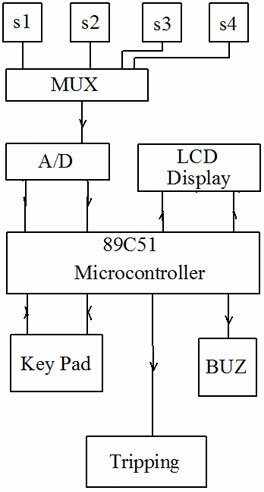
In our project we designed a circuit which contains a micro controller which collects the data from sensors placed at different locations of device & display them into LCD.
Now after collecting the data micro controller compares them with standard values (pre defined for each sensor on normal working conditions) & if it detects deviation from normal values it gives a buzzer sound & if it crosses the maximum limit it trip off the unit for a fixed duration & records the collected data into EEPROM.
Now if the number of tripping exceeds the 10 no. it permanently trip the unit & starts them only after detecting the password.
The utility of this circuit are:
- To warn the manufacturer at the initial stage of fault so that manufacturer can take proper corrective action before serious damage to device occurs which saves a lot of money required to reconstruct the device and other associated losses.
- Performance observation of the device.
- Monitoring of the device.
Block Diagram Explanation

A) Sensors:
This is the part of circuit which senses the different parameters of the unit.
To make the circuit unit independent it is necessary to use a conditioning unit between sensor & multiplexer. The conditioning unit will automatically maintain the output level of signals between desired limits.
B) Multiplexer:
This is required to select sensors one by one for analog to digital conversion of their values (output). When we are using single ADC the multiplexer must be analog in nature because we have to connect the analog signals.
C) A/D Converter:
This unit converts the analog signals coming from multiplexer in to 8bit parallel digital data which is a must for Micro controller operation because Micro controller can not work with analog signals directly.
D) Micro controller:
As the name indicates this unit has the over all command of all blocks or this unit decides when to use & which unit has to be used. Since it is a programmable device it provides the facility to update the device without changes in hardware & it also reduces the hardware required to implement the circuit.
E) LCD Display:
Display plays an important role whenever we want a user friendly system because user can see & read the information from display & can get better understanding about the system. Since we want to display alphabets for massages & digits for readings we required a alphanumeric LCD display so we use a 16 character , 2 line display best suitable for our requirement because our massage length to not greater then 16 character, so they can be displayed on single line only.
F) EEPROM R/W
As we consider a SIM it’s a memory card or ROM which can be erased electrically because many EEPROM requires different voltage levels to program, we need a voltage level shifter or Converter to interface it with microcontroller which have only two level outputs 5VDC & 0V DC.
G) EEPROM
It’s a two terminal memory device which stores the Information about the energy in a predefined format it contains 10, 8bit number interrelated by some mathematical function so that it can not be charged by unauthorized persons although we have used here a chip which can be used for 256 bytes of memory so that in future we can incorporate some additional features also in same card.
H) Key Pad
This section consist the keys one to reset the controller & other one to provide the password.
I) Indications & Beeper
Although we are using here a LCD display to display the information but it is still requirement of a system that it should create the special attention of user to read same specific information on LCD this is done by this block. It generates a beeping sound on over loading mode. So that user need not to read the LCD frequently (when not required).
J) Relay & tripping unit
To disconnect the supply when tripped.

hello,
sir i m interested to buy this project.please tell me the cost of project
hi… i’m studying engg..i want to do this as my final year project.. plz provide me the details
i… i’m studying engg..i want to do this as my final year project.. plz provide me the details
hi,can i get some more details about this project…
hi,plz give details about heavy electrical device protector project ,as soon as possible.
dear sir,
Please send your budgetary offer of project including , technology transfer, on my email address niyatiengineers@gmail.com.
hi, pls give more details about heavy electrical device protector project
hi, pls give more details about this project
sir,
iam intrusted with your projects i want to do same project for my
self so i kindly requested to please provide necessary data for project
and iam waitng for your reply
sir,
i alredy requested for the Heavy electrical device protector data for self
i want to do a project on this plz help me my id laksh.laxman@gmail.com