There are four ports P0, P1, P2 and P3 each use 8 pins, making them 8-bit ports. All the ports upon RESET are configured as output, ready to be used as output ports. To use any of these ports as an input port, it must be programmed.
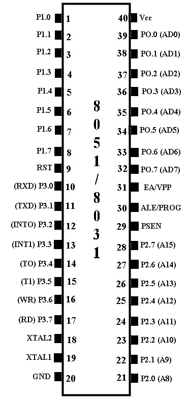
Pin configuration of 8051/8031 microcontroller.

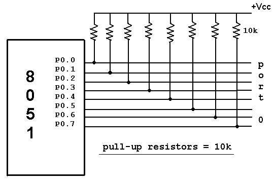
Port 0: Port 0 occupies a total of 8 pins (pins 32-39) .It can be used for input or output. To use the pins of port 0 as both input and output ports, each pin must be connected externally to a 10K ohm pull-up resistor. This is due to the fact that P0 is an open drain, unlike P1, P2, and P3.Open drain is a term used for MOS chips in the same way that open collector is used for TTL chips. With external pull-up resistors connected upon reset, port 0 is configured as an output port. For example, the following code will continuously send out to port 0 the alternating values 55H and AAH
MOV A,#55H
BACK: MOV P0,A
ACALL DELAY
CPL A
SJMP BACK
Port 0 as Input : With resistors connected to port 0, in order to make it an input, the port must be programmed by writing 1 to all the bits. In the following code, port 0 is configured first as an input port by writing 1’s to it, and then data is received from the port and sent to P1.

MOV A,#0FFH ; A = FF hex
MOV P0,A ; make P0 an input port
BACK: MOV A,P0 ;get data from P0
MOV P1,A ;send it to port 1
SJMP BACK
Dual role of port 0: Port 0 is also designated as AD0-AD7, allowing it to be used for both address and data. When connecting an 8051/31 to an external memory, port 0 provides both address and data. The 8051 multiplexes address and data through port 0 to save pins. ALE indicates if P0 has address or data. When ALE = 0, it provides data D0-D7, but when ALE =1 it has address and data with the help of a 74LS373 latch.
Port 1: Port 1 occupies a total of 8 pins (pins 1 through 8). It can be used as input or output. In contrast to port 0, this port does not need any pull-up resistors since it already has pull-up resistors internally. Upon reset, Port 1 is configured as an output port. For example, the following code will continuously send out to port1 the alternating values 55h & AAh
MOV A,#55H ; A = 55 hex
BACK: MOV P1,A ;send it to Port 1
ACALL DELAY ;call delay routine
CPL A ;make A=0
SJMP BACK
Port 1 as input: To make port1 an input port, it must programmed as such by writing 1 to all its bits. In the following code port1 is configured first as an input port by writing 1’s to it, then data is received from the port and saved in R7 ,R6 & R5.
MOV A,#0FFH ;A=FF HEX
MOV P1,A ;make P1 an input port by writing all 1’s to it
MOV A,P1 ;get data from P1
MOV R7,A ;save it in register R7
ACALL DELAY ;wait
MOV A,P1 ;get another data from P1
MOV R6,A ;save it in register R6
ACALL DELAY ;wait
MOV A,P1 ;get another data from P1
MOV R5,A ;save it in register R5
Port 2 : Port 2 occupies a total of 8 pins (pins 21- 28). It can be used as input or output. Just like P1, P2 does not need any pull-up resistors since it already has pull-up resistors internally. Upon reset,Port 2 is configured as an output port. For example, the following code will send out continuously to port 2 the alternating values 55h and AAH. That is all the bits of port 2 toggle continuously.
MOV A,#55H ; A = 55 hex
BACK: MOV P2,A ;send it to Port 2
ACALL DELAY ;call delay routine
CPL A ;make A=0
SJMP BACK
Port 2 as input : To make port 2 an input, it must programmed as such by writing 1 to all its bits. In the following code, port 2 is configured first as an input port by writing 1’s to it. Then data is received from that port and is sent to P1 continuously.
MOV A,#0FFH ;A=FF hex
MOV P2,A ;make P2 an input port by writing all 1’s to it
BACK: MOV A,P2 ;get data from P2
MOV P1,A ;send it to Port1
SJMP BACK ;keep doing that
Dual role of port 2 : In systems based on the 8751, 8951, and DS5000, P2 is used as simple I/O. However, in 8031-based systems, port 2 must be used along with P0 to provide the 16-bit address for the external memory. As shown in pin configuration 8051, port 2 is also designed as A8-A15, indicating the dual function. Since an 8031 is capable of accessing 64K bytes of external memory, it needs a path for the 16 bits of the address. While P0 provides the lower 8 bits via A0-A7, it is the job of P2 to provide bits A8-A15 of the address. In other words, when 8031 is connected to external memory, P2 is used for the upper 8 bits of the 16 bit address, and it cannot be used for I/O.
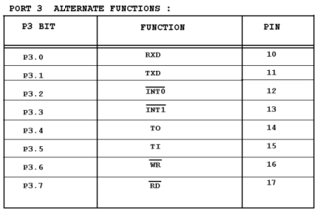
Port 3 : Port 3 occupies a total of 8 pins, pins 10 through 17. It can be used as input or output. P3 does not need any pull-up resistors, the same as P1 and P2 did not. Although port 3 is configured as an output port upon reset. Port 3 has the additional function of providing some extremely important signals such as interrupts. This information applies both 8051 and 8031 chips.

P3.0 and P3.1 are used for the RxD and TxD serial communications signals. Bits P3.2 and P3.3 are set aside for external interrupts. Bits P3.4 and P3.5 are used for timers 0 and 1. Finally P3.6 and P3.7 are used to provide the WR and RD signals of external memories connected in 8031 based systems.
Read-modify-write feature : The ports in the 8051 can be accessed by the read-modify-write technique. This feature saves many lines of code by combining in a single instruction all three action of (1) reading the port, (2) modifying it, and (3) writing to the port. The following code first places 01010101 (binary) into port 1. Next, the instruction “XLR P1,#0FFH” performs an XOR logic operation on P1 with 1111 1111 (binary), and then writes the result back into P1.
MOV P1,#55H ;P1=01010101
AGAIN: XLR P1,#0FFH ;EX-OR P1 with 1111 1111
ACALL DELAY
SJMP AGAIN
Notice that XOR of 55H and FFH gives AAH. Likewise, the XOR of AAH and FFH gives 55H.
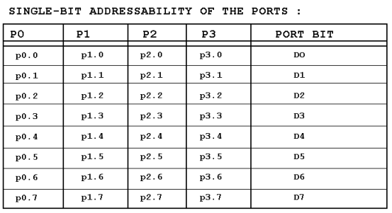
Single bit addressability of ports: There are times that we need to access only 1 or 2 bits of the port instead of the entire 8 bits. A powerful feature of 8051 I/O ports is their capability to access individual bits of the port without altering the rest of the bits in that port.
For example, the following code toggles the bit p1.2 continuously.
BACK: CPL P1.2 ;complement p1.2 only
ACALL DELAY
SJMP BACK
Notice that P1.2 is the third bit of P1, since the first bit is P1.0, the second bit is P1.1, and so on. Notices in example of those unused portions of port1 are undisturbed. Table bellow shows the bits of 8051 I/O ports. This single bit addressability of I/O ports is one of the features of the 8051 microcontroller.


GIVE ME SUM MOR DETAILS BOUT AUTOMATIC RAILWAY GATE CONTROL
what is the purpose of pull up resistors ?
Why pull up are resistors are connected externally to port 0?
Why pull up resistors are present internally in port1 ,port2 and port3 but in case of port 0 they are connected externally?
What is open drain cmos and how it is related to port 0?
give me some more details on rd and wr operation on this 8051 and also about p3.5 & p3.6
sir i designed the circuit that is given in stepper motor control board but the program that u gives that is incorrect pls send me the modify program for stepper motor control
Dear sir,
please tell me why me why pull-up register is required in 8051 port 0 ? .and please tell me which book is good for beginner .
reply soon i want waiting for your reply
Santosh Sharma
B.Tech ECE
Dear sir,
please tell me why pull-up register is required in 8051 port 0 ? .and please tell me which book is good for beginner .
reply soon i want waiting for your reply
Santosh Sharma
B.Tech ECE
March 10th, 2009
Please i need to be proficient in 8051 programing. How do i go about it.
yeah. what the best for beginner?
pls i need to learn about some microcontroller sub-routines such as delay etc
Dear sir,
please tell me which book is good for beginner .
reply soon i want waiting for your reply
sir please tell me which book is good for beginner .
8051 Microcontroller by Mazidi and Mazidi
and The 8051 Microcontroller Kenneth Ayala are good books for 8051 Microcontroller.
Pull up registers are connected to make out put high.
P1, P2, and P3 have internal pull-up resisters, So these arenot open drain.
P0 has no internal pull-up resistors and does not
connects to Vcc inside the 8051.
To use it as port we need to connect pull up resister. So output will be high.
Hi,
I need some info about dual role of port.
For making the port input enabled i need to send the data 0xFF to that port, i.e. bit 1 to each pin.
My doubt is, if i wanted to send 0xFF data to port as output signal then what will happened? Will it enable the port for input or will it send that signal properly.
I wanted to know how exactly micro controller differentiate between output data signal and latch signal.
please show that pullup resister and pull down resister….
why manufacturers left port 0 without internal pull up resistors?
first tell me why port0 of 8051 does-not have pull up resistors?
Pull up resistor is required to pull the input values up to a desired level (means 1) . initially the input value to port 0 is floating i.e don’t know either 0 or 1 . so if we want to input value we should use pull up resister and if we want 0 input value then we should use pull down resister.
best book for 8051 is mohmad ali mazidi.
sir,
please send me the 8051 progrms for sorting of data bytes in
ascending/descending order using bubble sorting technique,along
with comments.
Also please me the SOME program to realize the boolean expression
USING BIT MANIPULATION INSTRUCTIONS(PLEASE SEND COMMENTS
ALSO).
SIR,I AM A BEGINNER OF 8051 PROGRMMING.SO PLESE SEND ME THE
SOURCE CODE
sir i want the coding in c language .please help if possible .m doing programming for microcontroller based caller id …
please correct, all ports will be in INPUT STATE on reset.
sir,
i need 7segment to dotmatrix display conversion and pheripheral interfacing
Re: Why do some ports have a pullup resistor, but others do not?
Short answer: ports with pullup resistors are optimized for output, ports without pullup resistors are optimized for input.
The pullup resistors allow ports to drive external cmos lines high or low. However, when the port is used for input, the pullup resistors will continuously conduct when the line is pulled low. This leads to heat and power waste. The no-pullup resistor ports allow an external chip to drive the lines high or low without a continuous current through the port.
Hope this helps.
I want to ask this Question
How the keypad could be read by the microcontroller using just one 8 bit input or input-output port.?
Please give me a direct and complete answer
Comfortably, the article is in reality the freshest on this laudable topic. I concur with your conclusions and will eagerly look forward to your coming updates. Just saying thanks will not just be enough, for the extraordinary clarity in your writing. I will instantly grab your RSS to stay privy of any updates. Fabulous work and much success in your business efforts!
pls give details about lcd ?
how to stay at one place ? also if i want to show humidity then how to show it?
Sir.i am doing ‘fastest finger first project’ based on AT8951.it must be programmed.so can u plz give me the c program for my project….
Plz send me the c program code for my fastest finger first project using Atmel8951
how to manipulate ports when to receive & transfer the data ,by writing code in c language . please explain in binary form.
hi
I want to interface a resisitor with a microcontroller.
I would actually like to interface some analog devices such as filters and amplifiers with a microcontroller without using an A to D converter.
Kindly inform me if that is possible and how it could be done.
Regards
Ramandeep Rana
please tell me why pull-up register is required in 8051 port 0 ? .and please tell me which book is good for beginner .
reply soon i want waiting for your reply
Mohitosh Biswas
hello
can u suggest some assemblers for micro controller programming…
i m doin project on device control using cellphone.i m usin mc-8951 in it.can u plz mail me details if any.
suppose we want to output data FF H to a port P1 and write
MOV P1, 0FF H
does this output FF or instead make P1 an input port
Tell me about the internal operation of ports when configuring
it as input and output port
hello sir
Sir can you help in c/c++ programming
for wireless water level indicator using 8951
Upon power up, the i/o pins are configured as………..
i want to study how to programm the ports
please refer me book for this topic
sir,
sir,
I am working on a atmel 2051 micro controller .i work on a c language programming.
sir,
I am working on a atmel 2051 micro controller .i work on a c language programming.
my actual probel i will explain it will be prectically,with as output of led..
if my input is
P3=0xff all led blinks but isted of
p3=0x30 ;pin3.4 & 3.5 led are blinks but
P3=0x03 or P3=0x0c ;my led is not blink pin3.0,3.1,3.2,3.3; not working as req…
i also use sbit for preticular glow bur pin3.0 to3.3 are not working in it also
in port 1 which are pheripheral devices i.e. moso miso sck
it’simple 1.7 volt led
sir ,
Sir,
I am programming on at2051 atmel microcontroller,
I connect push button switch and eprom24c02
my pin connection of 2051 is
pin1 connect via capacitor to eprom pin8
pin2 connect eprom pin 5(SDA)
pin3 connect to eprom pin 6(SCL)
pin4,5 use for oscillator
pin6 coneect to pushbutten swich
pin7,8,9 (not connected)
pin 10 ground
pin11,12,13 (not connected)
pin 14 ,15,16,17,18,19 connect to led
pin 20 supply
Eprom pin
pin 1 (not connected)
pin2,3,4 ground
pin5 2051 pin 2
pin6 2051 pin 3
pin7 ground
pin8 connect via capacitor to2051 (1) pin
swich othr terminal is grounded
my quary is i want to made a program to whaen switch pressed pattern change of led there is 15 pattern in my controller my eprom is not programeble
For the better understanding of PORT 0 and the concept of pull up register, check this out.
https://www.youtube.com/watch?v=t9bN-2nFNEs
pls send me the simple basic program using micro controller