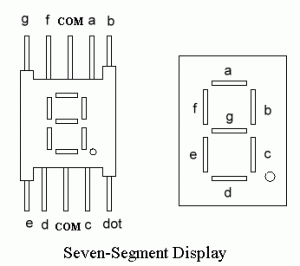
The Light Emitting Diode (LED), finds its place in many applications in this modern electronic fields. One of them is the Seven Segment Display. Seven-segment displays contains the arrangement of the LEDs in “Eight” (8) passion, and a Dot (.) with a common electrode, lead (Anode or Cathode). The purpose of arranging it in that passion is that we can make any number out of that by switching ON and OFF the particular LED’s. Here is the block diagram of the Seven Segment LED arrangement.
Pin configuration of a seven segment display:
LED’s are basically of two types:
- Common Cathode (CC)
All the 8 anode legs uses only one cathode, which is common. - Common Anode (CA)
The common leg for all the cathode is of Anode type.
For the discussion purpose, we use CC LED, where by just reversing the logical voltages we can implement the same for CA LED also.
In a CC LED, all the 8 legs (‘a’ through ‘h’) are of anode type and the common cathode will be connected to the GND of the supply. By energizing any of the legs with +5 Volts will lead to switch the correspondent segment ON. In the microprocessor binary system, 0Volts will be considered as Binary 0, and 5Volts will be considered as Binary1. Considering these two condition, we can make an arrangement as the microcontroller gives OUT the 0s and 1s through its ports, which is connected to the 8 legs of the LED. Of course, we can control the Port Output; implicitly we can Switch-ON required legs of the display.
There 2 methods of interfacing LED with the Microcontroller Intel 8051/8951.
- Using lookup table. This uses 7 output pins of microcontroller
- Using 7447 decoder. This method uses 4 output pins of microcontroller
The difference between the two main methods is simple and clear. In both the cases, microcontroller communicates with external world through its ports. But, in the 1st case, we connect all the 8 pins of the port directly to the LED and control the voltage through the ports manually to display the desired number. But, in the second case, we send the BCD of the number that we wanted to display to a middleware IC 7447, the BCD to LED code converter, which by itself gives out the correspondent 7 segment codes to the LED.
Here we explain using lookup table. Click here for the method “using 7447 decoder”
Using 7447 decoder:
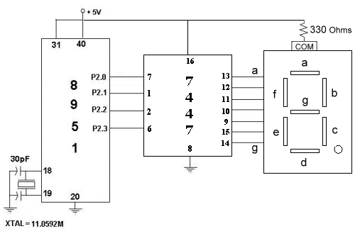
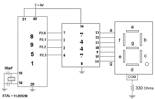
The IC7447 is a BCD to 7-segment pattern converter. This setup is the advanced form of the <previous> setup where we entered the patterns manually to display the desired character. Here in this case, the IC7447 takes the Binary Coded Decimal (BCD) as the input and outputs the relevant 7 segment code. We connect first four pins of the microcontroller Port 2 to the 7447 and the Output 8 pins of 7447 to the 8 legs of the LED as shown in the figure. Te circuit diagrams are shown below, the first figure is interfacing the CA LED where as the second is of CC LED. The number required to display is sent as the lower nibble of the Port 2 of the Microcontroller. The 7447 converts the four input bits (BCD) to their corresponding 7-segment codes. The outputs of the 7447 are connected to the 7-segment display.


Program:
This program displays characters 0 through 9 on seven-segment display using IC 7447 as the middle wear.
again: mov a,#00h ; Start form zero
       up: mov p2, a ; Move to Port 2
       mov r3,#255 ; Delay
D1:    mov r1,#255
D:     djnz r1,D
       djnz r3,D1
       inc a
       cjne a,#0ah,up
       sjmp again
how about the config of ic 555 in 7 segment diagram?????
Are all 7 segment displays pinned out this way, the same LEDs to the same pins?
why was 330ohm resistor included ??
I requied to Implement SSD with IC 7448.How do I?
if i use two 7447 ic’s having 2 common cathode and also apply 3 simple switches functions of switches are up,down and on/off …. then what’s the procedure of coding ? i want interface it with parallel port ….
i need it in urgent , do help me !!
Hai,
Whether it works with out using controller, I jut want it to
work by simply supplying power through driver. wht to do?
I want to know more about making led seven segment using c .
Can 7447 drive Common Cathode display also as shown above.
I think 7448 is used.Please clarify.
in case of common cathode display only difference being that coommn cathode terminal is connected to ground through 330 ohms bleeder and remaining circuit remains the same…
why we use 8951 micro controller if we are using only one segment of
display.we can easily give 1 or 0 to input of Binary to seven segment decoder ic
7447.it can also given by switches which toggle from 0 to 1 or 1 to 0.
simple why we make circuit complicated .Engineers means design the best circuit
in cheapest price and user friendly.
if you know anything else contact me my email
id is sujeetsingh02@yahoo.in.
i am from HRIT ghaziabad uttar pradesh India
in the 7447 RBI and RBO, what indicate???
why we use 8951 micro controller if we are using only one segment of
display.we can easily give 1 or 0 to input of Binary to seven segment decoder ic
7447.it can also given by switches which toggle from 0 to 1 or 1 to 0.
and i think we can use ic 7448….pls clarify
my id is snehamoharir123@gmail.com
how to configure 7 seg dip. by using 74147 and 7447
how to make it?
if i were to use an external gate to make some changes in the display,where should i put it???is it on the input??or output???
hello,
Im new to this 7-segment display i want to ask some questions..
how to interface a micro-controller to a multiple seven segment display?
say 10 7-segment display? do i have to use latches and decoder/multiplexer
for this? hoping for your king reply…
hi
can any one help me with what kind of seven segment display i use which is compatible with msp430f2122 controller.you can mail me on rakshasingh011@gmail.com
can you help me of seven segment
from where can I got the internal circuit diagram of BCD decoder? Plz help me.
Please kindly give me the circuit diagram of the Digital substitution board with LCD display of two digit on one side or two sided for a football substitution.
Please kindly give me the circuit diagram of the Digital substitution board with LCD display of two digit on one side or two sided for a football substitution OR direct me where to get the design and construction of this substitution board.
hi…
i m new here..can anyone tell me how to design a decoder to display binary numbers using 7-segment display
تفاوت تراشه 7447 و 7446؟
hey i m 12th grade student and want to know how does one make a decoder which shows the digit’s from 1 to 5 one who knows can please mail me at my ID bsandyfriends@gmail.com
-thanks
That’s wonderful. Could please send a circuit for 2 x 7 segment LEDs or two digit display with 7447 and 74148? Thanks
kindly check the circuits b4 putting them online!!! pls do not give wrong info in the excitement of posting something!! the second circuit is such a blunder…. it doesnt work at all!!
i want’s to give input to 7447 from the basic gates. is it possible to get bcd equivalent on 7 segment display.
2) required 7 segment display is common cathod or common anode
is ic7447 works with common cathode circuit please help me…..!
my email id is ::kingsekar91.n@gmail.com
Нi, its pleasant post reɡarding media print, we all be aware of media is a fantastic source ߋf
data.
Hi guys, could u guys plz tell me which IC is appropriate for 7-segmet decoder to be used in a housing estate company which deals with sustainable building issues?