Flushing devices are put wherever there is a danger that sewer pipes will become blocked, such as in dead ends of sewers or in sewers planned out on flat gradients that do not provide self-cleansing velocities. These gadgets temporarily store water and dump it into the sewer so that it can be cleaned and flushed. These gadgets are referred to as flushing tanks. Flushing tanks ought to be able to store enough water, which might be adequate to clear the sewer system. This capacity typically corresponds to a depth of roughly one tenth of the sewer line’s cubical capacity that it serves.
Two types of flushing operations are normally used
(1)Flushing operation using automatic flushing tank
(2) Hand operated flushing operation
Automatic flushing tanks
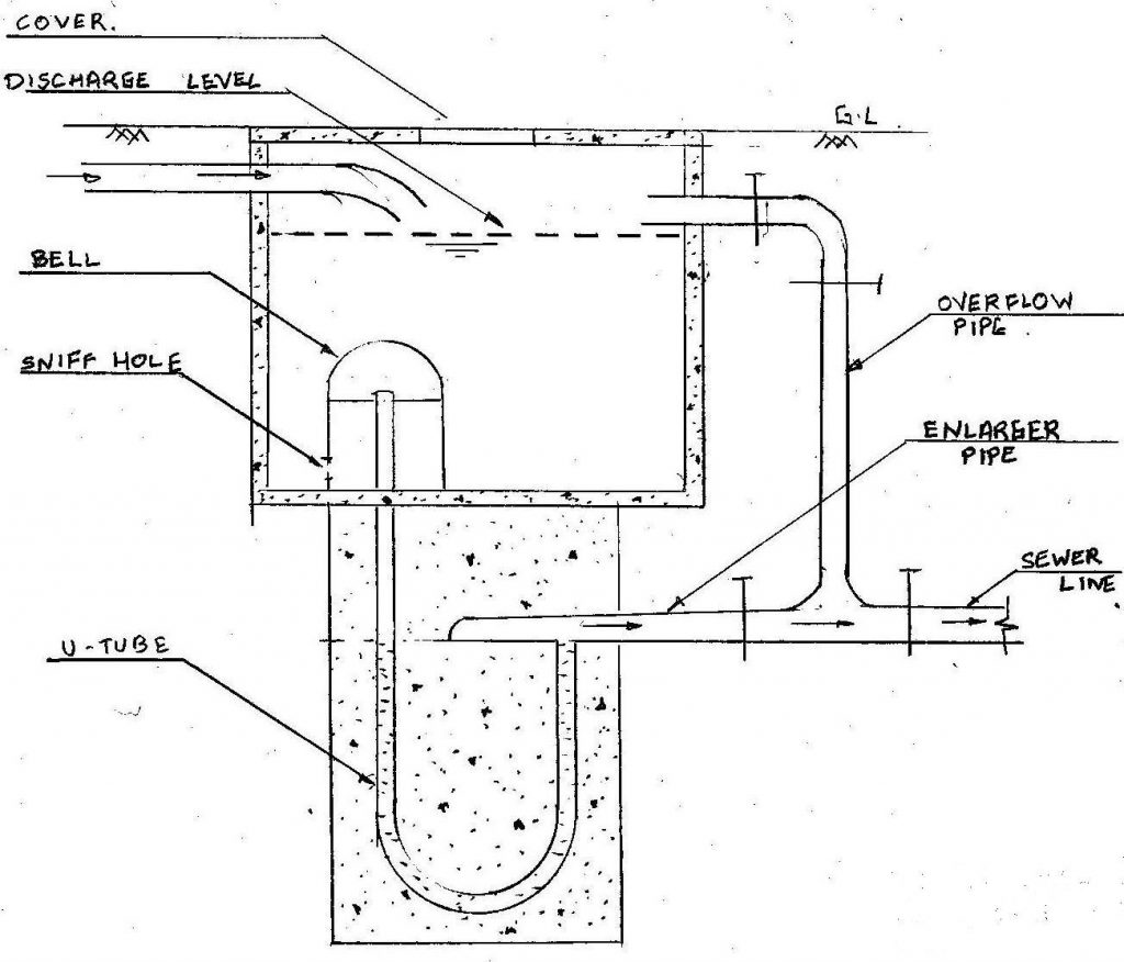
This kind of flushing tank performs the flushing process automatically and on a schedule. The water entry is controlled in such a way that it fills the tank to the discharge point in a time that is equivalent to the flushing interval. In the event that the tank does not discharge properly and overflows, water can be drained away using an overflow pipe. Following is a description of how an automated flushing tank functions: The water level in the U-tube is initially between A and B when the tank is empty. The water level in the tank gradually increases as the water arrives through the entrance pipe. Until the water level in the tank stays below the level of the sniff hole, the water level in the U-tube stays at this level, or A-B. But the air is trapped and squeezed in the bell part as the water level in the tank rises over the level of the sniff hole. The water level in this along arm of U-tube is lowered as a result of the pressure that this compressed air exerts on surface A.
As the tank continues to fill up more and more, the water level continues to drop. A point is eventually reached when this occurs, a little amount of compressed air is released through the shorter arm of the u-tube, and an equivalent amount of water enters the bell. The adjustment is such that at this point the discharge line has just about been achieved, and the head of water above the bell exceeds that in the shorter arm of U-tube. When the compressed air is abruptly removed from the longer arm of the U-tube, a syphoning movement begins, allowing the water in the tank to flow into the bigger pipe and into the sewer. Up until the water level in the tank reaches the sniff hole, the siphonic activity is still in motion. The siphonic process is subsequently broken when the air enters the bell part through the sniff hole. The water level in the U-tow tube’s arms once more assumes positions A and B. the cycle continues, releasing water into the sewer on a regular basis.
Hand Operated Flushing Operations
In one way, the sludge entering the manhole from the inlet end will begin to gather in the manhole after the exit end of the manhole is closed by a sluice valve, etc. When enough sewage builds up, the manhole’s outlet end is quickly opened, allowing the sewage to enter the sewer and starting the flushing process.
Another approach allows water from the outside to enter the manhole by closing both the intake and outflow ends of the manhole with sluice valves, etc. The outputs and inlet ends can then be opened to perform the sewer flushing.
In a different technique, a nearby fire hydrant is attached to one end of a hose pipe, and the other end is then inserted into the manhole to perform the flushing action.